 English
 Español
 Deutsch
-
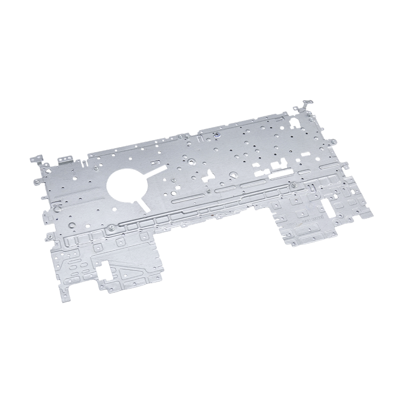
Laptop stamping parts
Our laptop stamping parts are precision-manufactur...
-
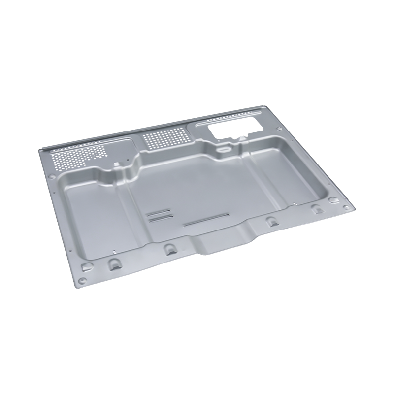
High-end oven stamping parts
Our High-end oven stamping parts are precision-man...
-
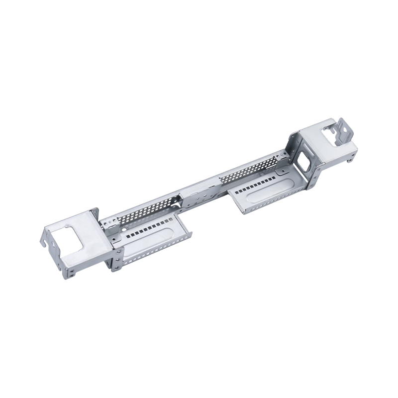
High-end large computer stamping parts
Our High-end large computer stamping parts are pre...
-
Car seat stamping parts
Car seat stamping parts are core metal components ...
-
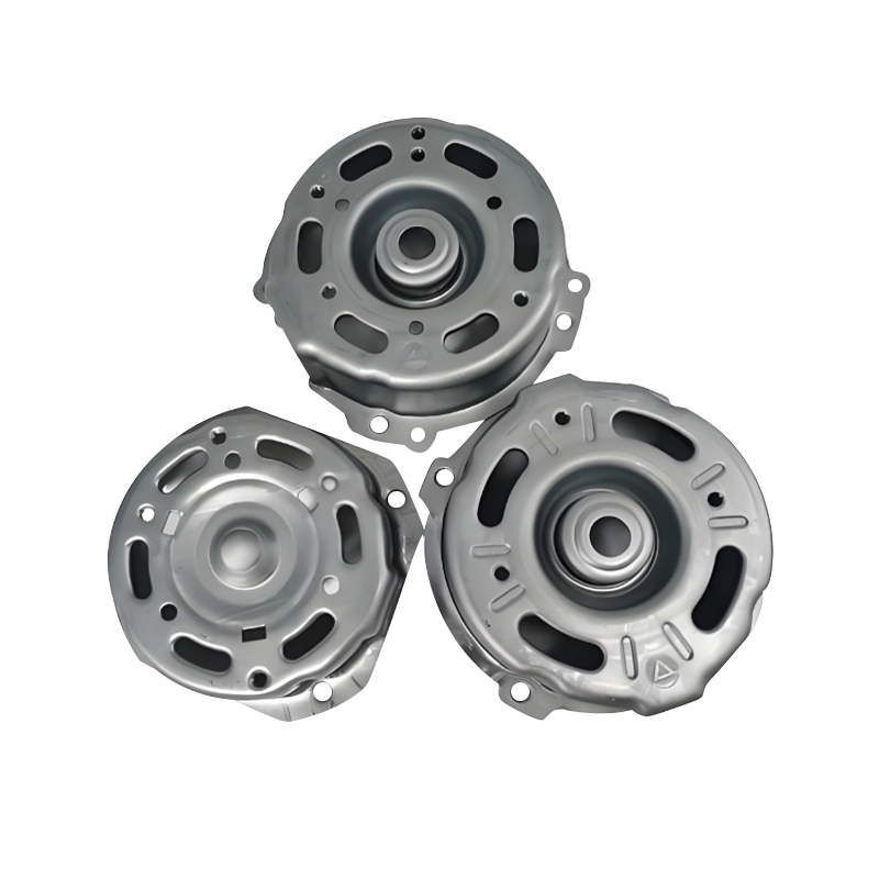
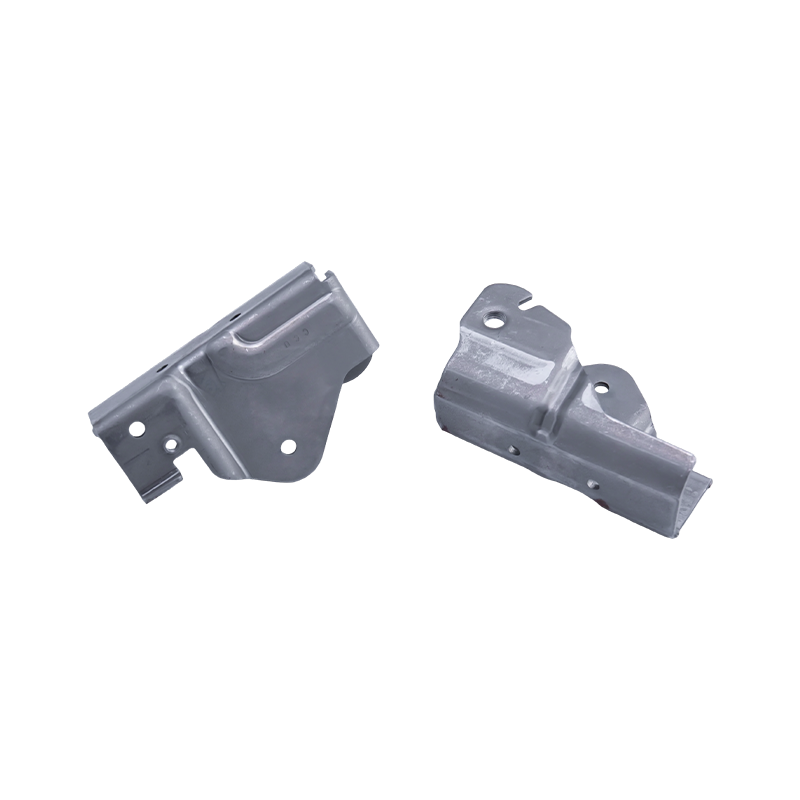
Automotive motor housing stamping parts
Automotive motor housing stamping parts are core c...
- E-mail us: [email protected]
- Call us: +86-139 1308 8972
Industry News
Home / News / Industry News / Why Do Electronic Stamping Dies Require Tighter Tolerances Than Home Appliance Stamping Dies?
Why Do Electronic Stamping Dies Require Tighter Tolerances Than Home Appliance Stamping Dies?
2026-02-25
Content
- 1 The Functional Gap That Drives Tolerance Differences
- 2 How Part Scale Amplifies the Precision Demand in Electronic Stamping Dies
- 3 Die Construction Differences That Reflect Tolerance Requirements
- 4 Material Considerations That Tighten the Tolerance Chain
- 5 Press Requirements and Environmental Controls for Electronic Stamping Dies
- 6 Verification and Quality Assurance: A Higher Bar for Electronic Stamping Dies
The Functional Gap That Drives Tolerance Differences
The tolerance requirements of any stamping die are ultimately derived from what the finished part must do in service. Home appliance stamping dies produce components — washing machine drum panels, refrigerator door shells, air conditioner chassis brackets, and microwave oven housings — where the primary performance criteria are structural rigidity, corrosion resistance, surface appearance, and fit within an assembly that is assembled by human hands with mechanical fasteners. The dimensional tolerances that govern these parts typically fall in the ±0.1mm to ±0.3mm range for general profile dimensions, and ±0.05mm for critical hole locations and flange interfaces. These are meaningful precision requirements, but they reflect the assembly realities of large sheet metal enclosures where a few tenths of a millimeter of positional variation can be absorbed by fastener clearance holes, sealant beads, or the inherent compliance of thin sheet metal panels.
Electronic stamping dies, by contrast, produce parts whose dimensional accuracy is directly coupled to electrical, mechanical, or electromagnetic performance. A connector terminal stamped to carry 5A of current through a 0.3mm-thick phosphor bronze strip must maintain a contact force within a precisely defined range — too little force and the connection becomes resistive or intermittent, too much and the mating connector cannot be inserted or the terminal fatigues prematurely. That contact force is determined by the spring geometry of the terminal, which is set by the bend radius, the angle, and the developed length of the strip — all of which are controlled to tolerances of ±0.01mm to ±0.02mm in a well-designed electronic stamping die. A motor lamination stamped from silicon steel must maintain a slot width tolerance of ±0.015mm to ensure that the rotor-to-stator air gap is uniform around the circumference, because non-uniform air gaps create unbalanced magnetic pull that reduces efficiency and generates vibration. These are not conservative engineering margins — they are the minimum precision levels at which the electronic device functions within its specification.
How Part Scale Amplifies the Precision Demand in Electronic Stamping Dies
Scale is one of the most important — and most underappreciated — reasons why electronic stamping dies require tighter absolute tolerances than home appliance stamping dies. A washing machine drum panel might measure 600mm × 500mm, and a positional tolerance of ±0.2mm on a mounting hole represents a relative precision of 1 part in 3,000 relative to the part's largest dimension. A USB-C connector terminal might measure 8mm × 2mm overall, and a positional tolerance of ±0.02mm on a contact beam represents a relative precision of 1 part in 400 relative to the part's largest dimension — nearly eight times tighter in relative terms, and achieved on a part that is 75 times smaller in area. Maintaining that level of precision requires every element of the electronic stamping die system — the die steel, the guide posts, the punch holder, the stripper plate, and the press itself — to perform at a level that would be unnecessary and uneconomical for home appliance stamping dies.
The miniaturization trend in consumer electronics has intensified this challenge continuously over the past decade. Terminal pitches that were 2.54mm (0.1 inch) twenty years ago are now commonly 0.5mm or 0.4mm in fine-pitch connectors, and the stamped features that create the contact geometry at those pitches — beam width, slot width, embossment height — must be controlled to tolerances that are a fixed fraction of the feature size. As feature sizes shrink, the absolute tolerance shrinks proportionally, even if the relative precision requirement stays constant. This is why investment in electronic stamping dies has consistently demanded higher tooling costs, finer die steels, and more rigorous metrology than home appliance stamping dies of the same vintage.
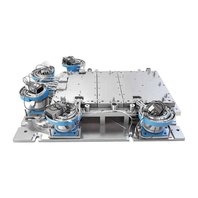
Die Construction Differences That Reflect Tolerance Requirements
The physical construction of electronic stamping dies reflects their tighter tolerance requirements in several specific and measurable ways. The following table compares the key construction parameters between typical home appliance stamping dies and electronic stamping dies across the most tolerance-sensitive design elements.
| Design Element | Home Appliance Stamping Dies | Electronic Stamping Dies |
| Punch-to-die clearance (per side) | 8–12% of material thickness | 3–6% of material thickness |
| Guide post fit tolerance | H6/h5 (±0.008mm) | H5/h4 (±0.003mm) |
| Die steel hardness (cutting sections) | 58–60 HRC (SKD11 typical) | 62–64 HRC (DC53, SKH51 typical) |
| Punch position tolerance | ±0.02mm | ±0.005mm |
| Surface finish on cutting edges | Ra 0.4–0.8 µm | Ra 0.1–0.2 µm |
| Primary machining process for inserts | CNC milling + grinding | Wire EDM + coordinate grinding |
| Resharpening interval (typical) | 300,000–500,000 strokes | 500,000–1,000,000 strokes (harder steel) |
The tighter guide post fit in electronic stamping dies is not merely a conservative engineering choice — it directly controls the lateral position of the punch relative to the die opening at the moment of contact with the material. At a punch diameter of 0.4mm blanking a hole in a 0.15mm-thick copper alloy strip, a lateral displacement of 0.003mm at the punch tip represents 2% of the punch diameter and 4% of the material thickness. At those scales, guide post slop that would be completely inconsequential in a home appliance stamping die becomes the dominant source of burr height variation and punch breakage risk.
Material Considerations That Tighten the Tolerance Chain
Home appliance stamping dies most commonly process cold-rolled steel, galvanized steel, and occasionally aluminum alloys in gauges of 0.5mm to 2.0mm. These materials have well-characterized, relatively consistent mechanical properties within a heat lot, and their springback behavior — while real — is predictable enough to compensate for in the die design using standard overbend or restrike techniques. The incoming material thickness tolerance for commercial cold-rolled steel is typically ±5% of nominal, and because the formed features in home appliance parts are large relative to the thickness variation, this variability rarely propagates into a meaningful dimensional problem in the finished part.
Electronic stamping dies most commonly process copper alloys, phosphor bronze, beryllium copper, and precision cold-rolled steel or silicon steel in gauges of 0.05mm to 0.5mm. Copper alloys used for electronic terminals are typically specified to precision thickness tolerances of ±1–2% rather than the ±5% standard for structural steel, because the spring geometry of a contact terminal is so sensitive to thickness that a 5% thickness variation would produce unacceptable scatter in contact force. Even within that tighter incoming tolerance, the die must be designed to accommodate the full range — which means that forming punch radii, cavity depths, and bend allowances must be calculated and verified with material property data specific to the actual alloy and temper being run, not generic assumptions from a materials handbook.
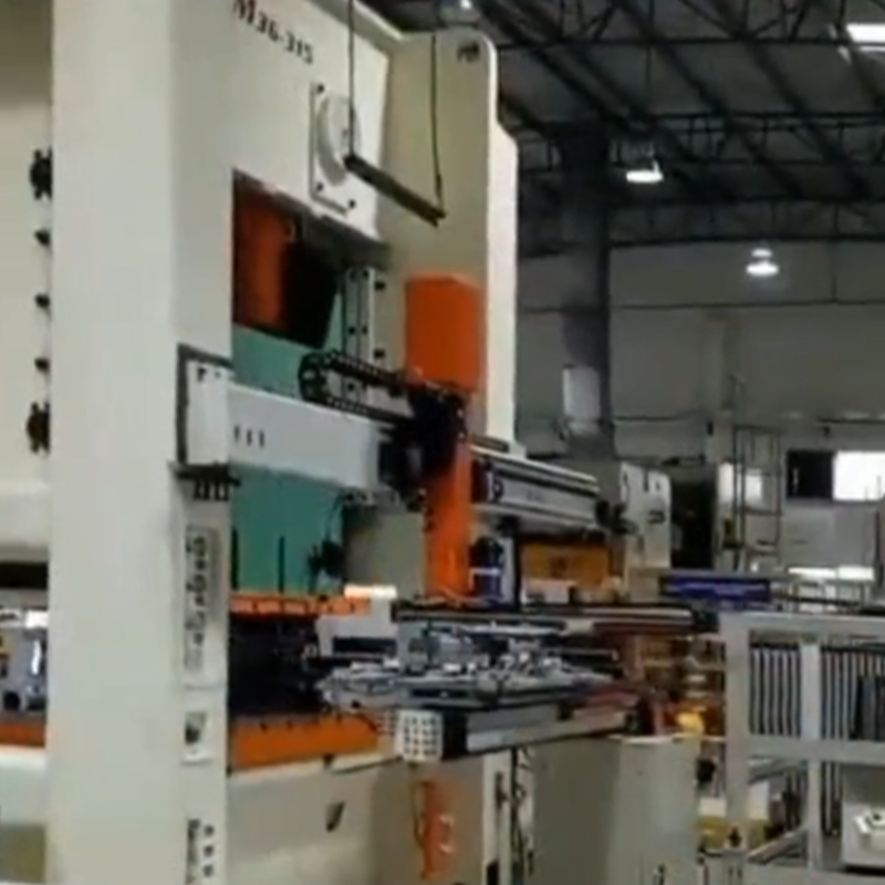
Press Requirements and Environmental Controls for Electronic Stamping Dies
The precision of electronic stamping dies is only as good as the press and environment in which they operate. High-speed precision presses used for electronic connector and terminal stamping incorporate several features that are unnecessary for home appliance stamping dies operating at lower speeds and coarser tolerances. These include hydraulic overload protection that stops the press within a fraction of a stroke if an abnormal load is detected — protecting dies with punches as fine as 0.3mm in diameter that would shatter under a misfeed load — as well as thermal compensation systems that adjust the press shut height to account for thermal expansion of the press frame during a production run. A steel press frame will expand by approximately 0.01–0.02mm per degree Celsius of temperature rise; for a home appliance stamping die running at ±0.1mm tolerance this is insignificant, but for an electronic stamping die running at ±0.01mm tolerance a 10°C frame temperature rise introduces a shut height error of 0.10–0.20mm that will shift the punch penetration depth and alter the formed feature geometry measurably.
Temperature-controlled die rooms are used by precision electronic stamping die manufacturers for this reason — not as a luxury but as a practical necessity for maintaining dimensional stability during both die manufacturing and production. The metrology equipment used to verify electronic stamping die components — air gauges, laser scanning systems, and coordinate measuring machines — must also be operated in temperature-controlled environments because their own calibration is sensitive to the same thermal effects that destabilize the die dimensions.
Verification and Quality Assurance: A Higher Bar for Electronic Stamping Dies
The inspection and verification requirements for electronic stamping dies and their output parts reflect the tighter tolerance regime in every aspect of the quality process. For home appliance stamping dies, first-article inspection typically involves manual measurement of critical hole locations, flange heights, and profile dimensions using calipers, height gauges, and go/no-go plug gauges — a practical and cost-effective approach for parts where the critical dimensions number in the dozens and tolerances are in the ±0.1mm range. For electronic stamping dies, first-article inspection routinely requires full CMM measurement of every contact geometry feature, optical comparator verification of punch and die contours, and functional testing of sample parts — such as contact force measurement for terminals or magnetic flux measurement for laminations — that confirms the stamped geometry is producing the required functional performance, not just meeting the dimensional drawing.
- Burr height on electronic terminal blanked edges is measured with calibrated optical microscopy, typically verifying that maximum burr height does not exceed 10% of material thickness — a specification that requires measurement resolution of 0.003–0.010mm, well beyond the capability of manual measurement tools used for home appliance parts.
- Coplanarity of contact surfaces across a multi-pin connector terminal strip is verified using laser profilometry or vision-based height mapping rather than manual height gauge comparison, because the tolerance is typically ±0.015mm across a span of 10–20mm and the required measurement uncertainty must be less than 30% of the tolerance — demanding sub-micron measurement capability.
- Statistical process control charts for electronic stamping production are configured with control limits set at ±2σ of the process rather than the more common ±3σ, because the ratio of process capability to tolerance is intentionally kept narrow to provide early warning of die wear before any out-of-tolerance parts are produced.
The investment required to design, build, verify, and maintain electronic stamping dies at this level of precision is substantially higher than for home appliance stamping dies — in tooling cost, equipment investment, and skilled labor. That investment is justified by the functional consequences of dimensional non-conformance: a home appliance part that is 0.1mm out of position may require a slightly oversized clearance hole, but an electronic terminal that is 0.02mm out of position may fail its mating connector insertion force test, triggering a full production lot rejection and a field reliability risk that neither the manufacturer nor their customers can accept.
Previous Post
How Do Advanced High-Strength Steels Change Automotive Stamping Parts Manufacturing?
Next Post
Cost Comparison: Metal Stamping Parts VS Metal Drawing Part Products in 2026
Our Products.
Start Your Business with an OEM Manufacturer Right Here!
Provide global customers with complete turn-key solutions
through
innovation!
QUICK LINKS
CONTACT INFO.
-
 +86-139 1308 8972
 -

-
 No. 118 Yexin Road, Wujiang Economic Development Zone, Suzhou, China
Copyright © Suzhou Shuangqisi Mold Equipment Co., Ltd. All Rights Reserved. Custom Stamping Die Metal Stamping Die Manufacturers
