 English
 Español
 Deutsch
-
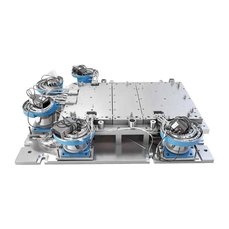
Automatic riveting mold for large computer machine base
This Automatic Riveting Mold for Large Computer Ma...
-
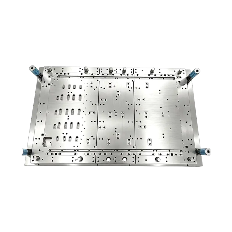
Multi-Station Progressive Stamping Die with Carbide Inserts Custom Multi Station Progressive Stamping Die Carbide Insert Metal Stamping Mold Tool for Equipment Appliances Device Hardware
High Speed Metal Stamping Tool for Precise Equipme...
-
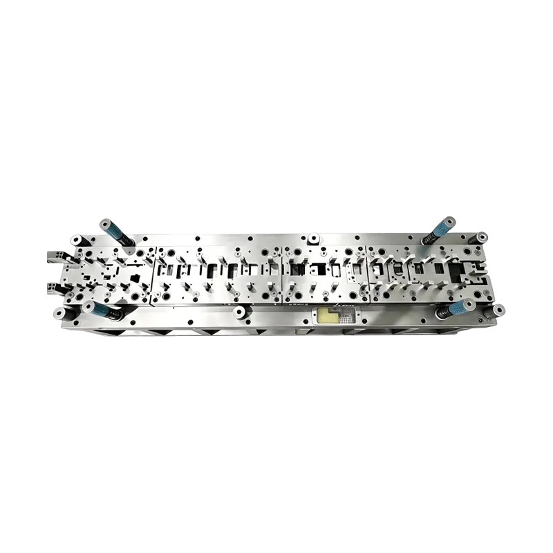
Long-Stroke Multi-Stage Progressive Die Automatic Strip Feed Progressive Die Long Travel Follow on Stamping Tool for Sheet Metal Hardware Press Moulding
Long-Stroke Multi-Stage Progressive DieOur custom ...
-

Deep drawing mold for front and rear wheels of two-wheeled electric vehicles
This Deep drawing mold for front and rear wheels o...
-
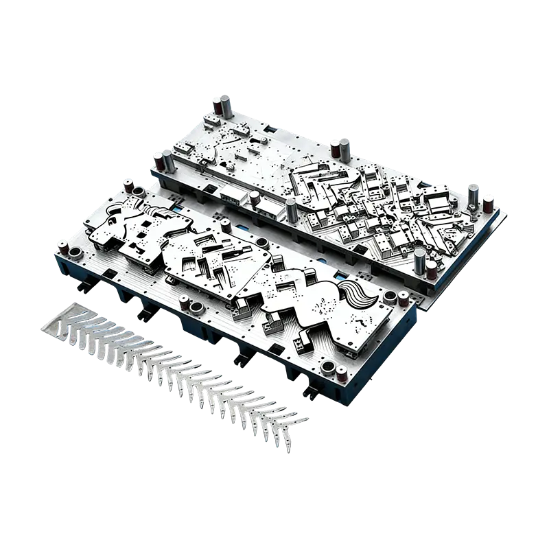
Progressive molds for automotive parts
This Continuous mold for automotive motor housing ...
-
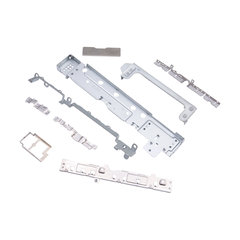
Small stamped parts for laptops and mobile phones
As essential internal components for modern portab...
- E-mail us: [email protected]
- Call us: +86-139 1308 8972

Industry News
Automatic Riveting Mold for Large Machine Base Assembly
2026-07-21
An automatic riveting mold designed for large computer machine bases transforms a traditionally labor-intensive, error-prone assembly step into a precision-controlled, automated process. By integrating a purpose-built mold with a robotic arm for rivet feeding and workpiece transfer, manufacturers can eliminate the manual positioning errors that lead to misaligned rivets, inconsistent joint strength, and rework rates that can reach 8–15% in manual operations. The mold's robust structure absorbs the stamping forces generated during rivet setting while maintaining precise alignment across the full footprint of a large machine base panel, which can measure 400 × 500 mm or larger. The result is consistent connection quality across every rivet joint, cycle times reduced by 40–60% compared to manual feeding and positioning, and direct integration into automated production lines where the robotic arm transfers completed workpieces to downstream stations without human intervention.

Content
- 1 How Automated Rivet Feeding Eliminates Positioning Errors
- 2 Mold Structure Designed for Large-Format Workpiece Stability
- 3 Stamping Force Uniformity and Connection Quality Assurance
- 4 Robotic Arm Integration and Production Line Connectivity
- 5 Defect Reduction Through Process Control and Error Proofing
- 6 Return on Investment and Production Efficiency Gains
- 7 Tooling Maintenance and Longevity Considerations
How Automated Rivet Feeding Eliminates Positioning Errors
Manual rivet placement depends on operator skill, fatigue level, and consistency over an eight-hour shift. Studies of manual riveting operations in sheet metal assembly show that positioning accuracy degrades measurably after 2–3 hours of continuous work, with error rates doubling in the final hours of a shift compared to the first hour. An automatic riveting mold integrated with a robotic arm removes this variability entirely. The robotic arm picks rivets from a vibratory bowl feeder or tape-fed dispensing system and delivers each rivet to the mold's precisely machined locating nests. These nests position the rivet within ±0.05 mm of the specified center point, a tolerance maintained across thousands of cycles without drift. The mold's locating pins and clamping elements simultaneously hold the workpiece—the large computer machine base panel—in a fixed reference position relative to the rivet axis. This coordinated positioning ensures that every rivet sits perpendicular to the mating surfaces before the stamping press descends, preventing the tilted or partially set rivets that account for the majority of manual assembly defects.
Rivet Feeding Sequence and Mold Integration
- The robotic arm retrieves a rivet from the feeding system using a vacuum gripper or mechanical jaw matched to the rivet head diameter, typically 3–8 mm for computer chassis applications.
- The arm moves to the mold and inserts the rivet shank into the designated locating bushing, releasing the rivet only after confirming insertion depth via a proximity sensor or vision system verification.
- The mold's clamping system activates, applying uniform pressure across the workpiece to prevent sheet movement during the stamping impact.
- The stamping press cycles, deforming the rivet shank or compressing the rivet head to form the permanent mechanical joint.
- After press retraction, the robotic arm picks the completed assembly and transfers it to the next station while simultaneously retrieving a fresh rivet for the next cycle.
Mold Structure Designed for Large-Format Workpiece Stability
Large computer machine bases present a specific challenge: their size means that riveting forces applied at one corner can cause the opposite corner to lift or shift if the mold does not provide full-perimeter support. The automatic riveting mold addresses this through a welded steel base plate with a thickness of 40–60 mm, stress-relieved after welding to prevent distortion during machining. This base plate provides a rigid reference plane onto which all locating elements, clamping units, and riveting nests are mounted. The mold incorporates hardened steel bushings at each riveting position—typically 8–20 positions per base panel depending on chassis design—with each bushing individually replaceable when wear exceeds 0.03 mm of diametral clearance. This modular design means that a single worn riveting station does not require complete mold replacement, reducing long-term tooling costs by allowing targeted refurbishment.
The clamping system uses pneumatic or hydraulic actuators distributed around the workpiece perimeter, applying a total clamping force of 2–5 kN distributed across the panel. The clamp locations are determined by finite element analysis of the sheet metal stiffness, ensuring that no area of the panel can vibrate or deflect during the riveting impact. For steel computer bases with sheet thicknesses of 0.8–1.5 mm, the riveting force per joint typically ranges from 8–15 kN depending on rivet diameter and material, and the mold structure must react these forces without measurable elastic deformation that could affect adjacent, already-set rivets.
Stamping Force Uniformity and Connection Quality Assurance
The quality of a riveted joint depends on the rivet being deformed to a specific geometry—whether a formed head height, an expanded shank diameter, or a controlled compression of the joined sheets. In manual or semi-automated processes, the press stroke is set once at the beginning of a batch, and variations in rivet hardness, sheet thickness, or press tonnage go undetected until quality inspection rejects finished assemblies. The automatic riveting mold can incorporate in-die force monitoring that measures the peak stamping force for each rivet cycle. This data is collected by a load cell mounted in the press ram or embedded in the mold's stripper plate, and the force signature is compared against an acceptable window—typically ±5% of the nominal peak force. A rivet that requires abnormally low force may indicate an undersized rivet or a missing sheet component; abnormally high force may indicate a double-fed rivet or foreign material in the joint. The control system can trigger an immediate alarm and stop the press before defective joints propagate down the production line, shifting quality control from end-of-line inspection to real-time process monitoring.
| Performance Metric | Manual Riveting | Automatic Riveting Mold | Improvement |
|---|---|---|---|
| Rivet Positioning Accuracy | ±0.5 mm (operator dependent) | ±0.05 mm | 10x improvement |
| Cycle Time per Rivet | 8–15 seconds | 3–5 seconds | 50–65% reduction |
| Defect Rate | 8–15% | 0.5–2% | 85–95% reduction |
| Joint Strength Variation (Cpk) | 0.8–1.0 | 1.33–1.67 | Process capability gain of 0.5+ |
| Operator Fatigue Impact | Significant after 2–3 hours | None (automated) | Consistent quality across full shift |
Robotic Arm Integration and Production Line Connectivity
The automatic riveting mold functions as one station in a connected production sequence, not as an isolated machine. The robotic arm that feeds rivets into the mold also serves as the workpiece handling system, transferring incoming panels from an upstream conveyor or pallet and removing completed assemblies to the next process station. This dual-function design—combining rivet feeding and part transfer—reduces the number of robots required on the line and simplifies the control architecture. A single robot controller manages both material handling and rivet delivery sequences, with the mold's clamping and press actuation coordinated through discrete I/O or fieldbus communication with the robot controller.
For large computer machine base production, the robotic arm is typically a six-axis articulated model with a reach of 1,200–1,800 mm and a payload capacity of 10–25 kg, sufficient to handle both the rivet gripper end-effector and the workpiece. The arm's repeatability of ±0.03–0.06 mm ensures that rivets are delivered to the mold nests and that completed panels are placed accurately on the outgoing conveyor or pallet. Vision systems at the mold confirm rivet presence and orientation before each press cycle, providing a final verification layer that catches any feeding anomalies before they produce defective assemblies. This closed-loop verification is particularly valuable for large machine bases where the cost of scrapping a fully processed panel—with multiple rivets already set—significantly exceeds the cost of the individual rivets and the cycle time lost to a rejected part.
Defect Reduction Through Process Control and Error Proofing
Human-induced defects in manual riveting stem from predictable sources: incorrect rivet orientation, missed positions, double-fed rivets, and inconsistent press dwell time. The automatic riveting mold eliminates each of these failure modes through integrated error-proofing measures. Rivet orientation is controlled mechanically in the feeding system: vibratory bowl feeders orient rivets by head diameter and shank length, rejecting any rivet that is upside down or dimensionally out of specification before the robotic arm picks it. Missed positions are prevented by the robotic arm's programmed sequence, which tracks completed rivet locations and will not advance to the next panel until every position has been addressed. Double-feeding is detected by the force monitoring system: a double-fed rivet requires abnormally high stamping force and triggers an immediate press stop. Inconsistent dwell time is eliminated because the press cycle is electronically controlled, maintaining the same contact duration for every rivet regardless of production speed.
The cumulative effect of these error-proofing measures is a defect rate that drops from the manual baseline of 8–15% to a sustained 0.5–2% in automated operation. The residual defects are primarily attributable to incoming material variation—rivet hardness outside specification or sheet metal thickness at the extremes of the tolerance band—which the force monitoring system identifies in real time, allowing the defective part to be quarantined immediately rather than discovered during final assembly or, worse, after the computer system is installed in the customer's facility.
Return on Investment and Production Efficiency Gains
The economic case for an automatic riveting mold rests on measurable improvements in three areas: direct labor reduction, defect-related cost avoidance, and throughput increase. A typical large computer machine base requires 12–20 rivets across its mounting points and structural reinforcements. With manual riveting at 10 seconds per rivet average cycle time including handling, a single panel consumes 120–200 seconds of direct labor. The automated system, with robotic handling and integrated rivet feeding, completes the same work in 60–100 seconds—a throughput improvement that allows one automated cell to replace two to three manual workstations. The labor savings are amplified by the elimination of rework labor: manual defect rates of 10% mean that one in ten panels must be partially disassembled, defective rivets drilled out, and the joint re-riveted, consuming additional labor that produces no additional output. When defect-related costs are included in the calculation, the payback period for a fully integrated automatic riveting mold system typically falls within 12–18 months for manufacturers operating two shifts producing computer chassis or similar large-format sheet metal assemblies.
Tooling Maintenance and Longevity Considerations
The mold's service life depends on the riveting forces involved and the abrasion resistance of the wearing components. Riveting bushings and locating pins, manufactured from tool steel grades such as D2 or M2 hardened to 58–62 HRC, typically withstand 500,000–1,000,000 cycles before requiring replacement. The mold base structure, being loaded within its elastic limit, has an indefinite service life with proper maintenance. A structured preventive maintenance schedule includes daily visual inspection of clamping elements and riveting nests for debris accumulation, weekly verification of locating pin positions using a coordinate measuring machine or calibrated master workpiece, and monthly replacement of pneumatic cylinder seals and verification of force monitoring system calibration. The modular design of the mold—with each riveting station individually replaceable—means that worn components can be swapped during a scheduled maintenance window without removing the entire mold from the press, keeping downtime to 2–4 hours per year for wear-related service. This predictable maintenance profile contrasts with manual operations where tooling wear often goes undetected until quality problems appear in finished products.
Previous Post
Deep Drawing Dies: Precision Metal Stamping for Hollow Parts
Next Post
Types of Stamping Dies: Progressive, Transfer & Deep Drawing Guide
Our Products.
Start Your Business with an OEM Manufacturer Right Here!

Provide global customers with complete turn-key solutions
through
innovation!
QUICK LINKS
CONTACT INFO.
-
 +86-139 1308 8972
 -

-
 No. 118 Yexin Road, Wujiang Economic Development Zone, Suzhou, China
Copyright © Suzhou Shuangqisi Mold Equipment Co., Ltd. All Rights Reserved. Custom Stamping Die Metal Stamping Die Manufacturers
