 English
 Español
 Deutsch
-
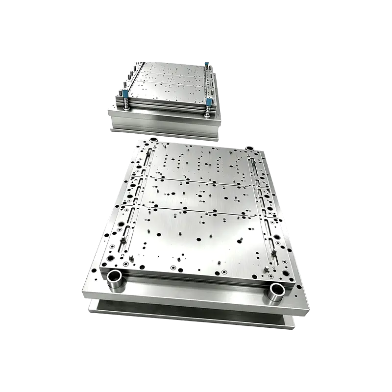
Progressive Stamping Die for Connector & Terminal Parts High Speed Progressive Stamping Die Precision Metal Hardware Stamping Tool mold for Connector Terminal Parts Automotive Components
Progressive Stamping Die for Connector & Termi...
-

Deep drawing mold for front and rear wheels of two-wheeled electric vehicles
This Deep drawing mold for front and rear wheels o...
-
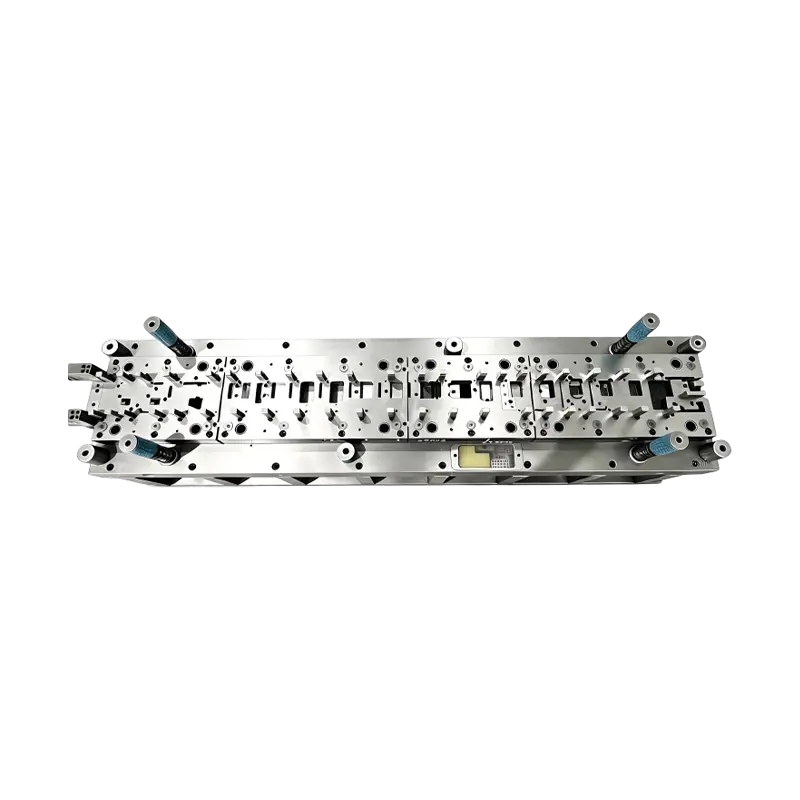
Long-Stroke Multi-Stage Progressive Die Automatic Strip Feed Progressive Die Long Travel Follow on Stamping Tool for Sheet Metal Hardware Press Moulding
Long-Stroke Multi-Stage Progressive DieOur custom ...
-
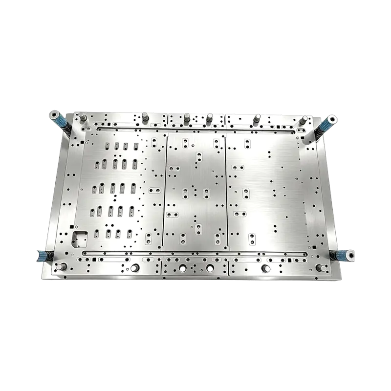
Multi-Station Progressive Stamping Die with Carbide Inserts Custom Multi Station Progressive Stamping Die Carbide Insert Metal Stamping Mold Tool for Equipment Appliances Device Hardware
High Speed Metal Stamping Tool for Precise Equipme...
-
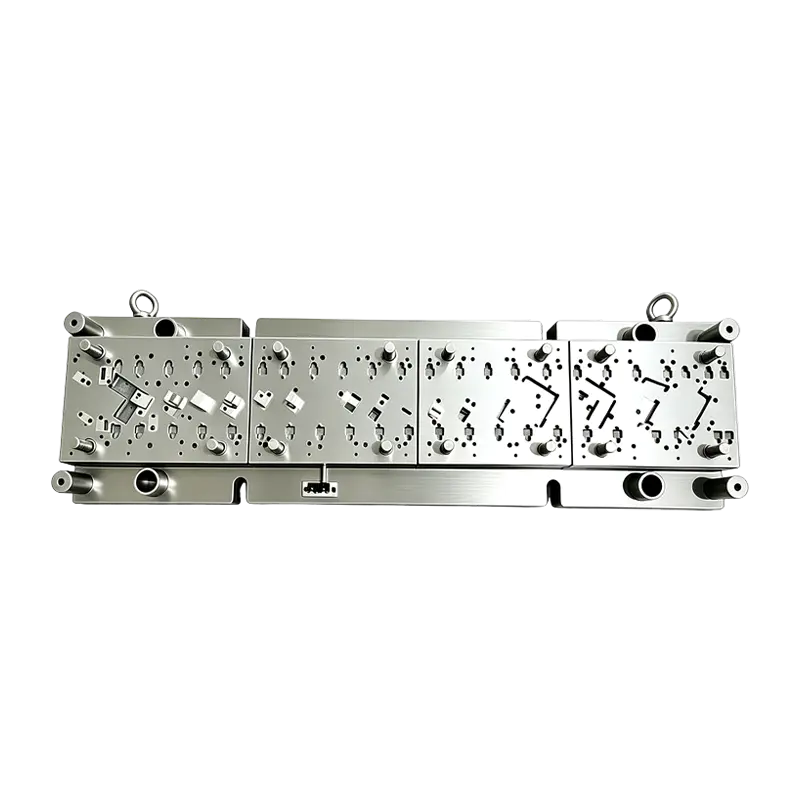
High Speed Progressive Stamping Die Sheet Metal Follow on Press Tool
Multi-operation Metal Stamping Tool for Continuous...
- E-mail us: [email protected]
- Call us: +86-139 1308 8972

Industry News
Deep Drawing Dies: Precision Metal Stamping for Hollow Parts
2026-07-29
Content
- 1 Controlled Material Flow: The Core Principle
- 2 How Deep Drawing Dies Achieve Shape Reduction Without Thickness Loss
- 3 Critical Process Parameters: Blank Holder Force and Die Clearance
- 4 Advanced Deep Drawing Processes
- 5 Die Structural Designs Tailored to Forming Stages
- 6 Extending Die Life Through Surface Engineering and Lubrication
- 7 Troubleshooting Wrinkling and Cracking
- 8 Applications: From Fuel Tanks to Enamel Basins
Controlled Material Flow: The Core Principle
Achieving a successful deep-drawn component hinges on one principle: controlled material flow. When a flat blank is drawn into a hollow shape, the metal must flow plastically without tearing or folding. Industry benchmarks show that maintaining a blank holder force between 1.5 and 2.5 times the material’s yield strength and setting a die clearance of 1.1 to 1.3 times the sheet thickness prevents the most common defects. This article examines the mechanisms, processes, and structural designs behind deep drawing dies.

How Deep Drawing Dies Achieve Shape Reduction Without Thickness Loss
Deep drawing fundamentally transforms a flat blank into a hollow part by reducing the diameter while maintaining a wall thickness close to the original sheet. The material in the flange region undergoes radial tensile stress and circumferential compressive stress, causing plastic flow into the die cavity. A well-designed process keeps thickness variation within ±10% of the initial gauge, ensuring structural integrity.
Critical Process Parameters: Blank Holder Force and Die Clearance
Two parameters dominate deep drawing quality: blank holder force (BHF) and die clearance. The BHF suppresses wrinkling in the flange; insufficient force leads to folds, while excessive force raises tensile stress and causes splitting. Die clearance provides room for the drawn wall—too tight increases friction and tearing, too loose reduces dimensional accuracy.
| Material | Sheet Thickness (mm) | Die Clearance (mm) | Typical BHF Pressure (MPa) |
|---|---|---|---|
| Mild Steel | 1.0 | 1.15 | 2.0 – 4.0 |
| Aluminum 5052 | 1.0 | 1.10 | 1.5 – 3.0 |
| Stainless Steel 304 | 1.0 | 1.20 | 3.0 – 5.0 |
| Copper C11000 | 1.0 | 1.10 | 1.5 – 2.5 |
Adjusting these values based on material drawability and part geometry is critical. For example, high-strength steels may require up to 30% higher BHF to control springback while keeping clearance at the upper bound to avoid galling.
Advanced Deep Drawing Processes
Initial Deep Drawing
The first draw transforms the blank into a cup. The punch nose radius and die entry radius are optimized to ease flow; typical ratios range from 4 to 10 times the sheet thickness. Multi-stage initial draws are common for deep parts like fire extinguisher bodies.
Thinning Deep Drawing
This process deliberately reduces the wall thickness by controlling a smaller clearance than the sheet gauge, improving strength-to-weight ratio. It is used for aerosol cans where wall thickness can be reduced by 30–40% through a series of ironing rings.
Reverse Deep Drawing
In reverse drawing, a pre-drawn cup is inverted and drawn in the opposite direction. This method compacts the grain structure and is ideal for symmetrical components like double-walled containers, reducing the number of intermediate anneals.
Die Structural Designs Tailored to Forming Stages
The architecture of a deep drawing die directly influences material flow and part quality. Three representative designs meet distinct technical demands.
Inverted Initial Deep Drawing Die
In this design, the punch is mounted on the lower shoe and the blank holder on the upper, using the press’s cushion system to apply controlled pressure. This setup simplifies blank feeding and ejection, often yielding cycle times of 15–25 strokes per minute for medium-sized automotive panels.
Blank Holder-less Reverse Deep Drawing Die
Suitable for low-profile parts, this die eliminates the blank holder and uses the draw bead and die geometry to restrain the flange. It reduces tooling cost and is frequently used for shallow sinks and housings where the draw ratio is less than 1.4.
Double-Die Thinning Deep Drawing Die
Featuring two consecutive ironing rings in a single stroke, this die achieves high wall thickness reduction without intermediate handling. It is standard in the production of beverage cans, maintaining a thickness tolerance of ±0.005 mm after ironing.
Extending Die Life Through Surface Engineering and Lubrication
Deep drawing dies endure high contact pressures and sliding friction. Surface treatments and proper lubrication dramatically extend service intervals. Common strategies include:
- Polishing die surfaces to a roughness of Ra 0.1 μm or below reduces friction and material pickup.
- Physical vapor deposition (PVD) coatings like TiN or CrN increase surface hardness to over 2000 HV and can extend die life by 3–5 times compared to uncoated tools.
- Diamond-like carbon (DLC) coatings provide a low coefficient of friction (≤0.1) for aluminum and stainless steel drawing, minimizing galling.
- High-performance drawing lubricants with extreme-pressure additives maintain a durable film under the 200–400 MPa interface pressures typical in deep drawing.
Troubleshooting Wrinkling and Cracking
Two primary defects—wrinkling and cracking—stem from improper parameter settings or tool wear. The list below correlates symptoms, root causes, and corrective actions.
- Wrinkling in flange or wall: Often due to insufficient blank holder force or excessive clearance. Increase BHF to 1.8–2.5× yield strength and verify die clearance is within 1.1–1.2× thickness.
- Bottom cracking (fracture at punch nose): Excessive BHF, tight punch radius, or poor lubrication. Reduce BHF, polish punch radius to ≥6× thickness, and apply high-viscosity lubricant.
- Splitting at the wall: Caused by material inclusions, insufficient die clearance, or worn draw beads. Increase clearance, inspect blank quality, and replace worn beads.
- Earing: Caused by planar anisotropy; control by rotating blank orientation or increasing draw ratio slightly. Limiting earing to under 2% is achievable with optimized textures.
Applications: From Fuel Tanks to Enamel Basins
Deep drawing dies produce parts requiring seamless, hollow geometries with consistent wall thickness. Automotive fuel tanks are typically deep-drawn from aluminized steel in multiple stages, achieving depth-to-diameter ratios of up to 2:1 without splitting. Kitchen sinks and enamel basins use single or reverse drawing to create smooth radii and avoid stress concentrations. Other examples include:
- Aerosol cans (thinning deep drawing)
- Fire extinguisher bodies (multi-stage initial drawing)
- Stainless steel cookware (blank holder-less or hydraulic forming)
- Electrical connector shells (micro deep drawing with foil thicknesses)
The choice of die design and process sequence is tailored to production volume, material grade, and geometric complexity, ensuring cost-effective high-quality output.
Previous Post
Car Seat Stamping Parts: High-Precision Metal Components
Next Post
Automatic Riveting Mold for Large Machine Base Assembly
Our Products.
Start Your Business with an OEM Manufacturer Right Here!

Provide global customers with complete turn-key solutions
through
innovation!
QUICK LINKS
CONTACT INFO.
-
 +86-139 1308 8972
 -

-
 No. 118 Yexin Road, Wujiang Economic Development Zone, Suzhou, China
Copyright © Suzhou Shuangqisi Mold Equipment Co., Ltd. All Rights Reserved. Custom Stamping Die Metal Stamping Die Manufacturers
