 English
 Español
 Deutsch
-

Deep drawing mold for front and rear wheels of two-wheeled electric vehicles
This Deep drawing mold for front and rear wheels o...
-
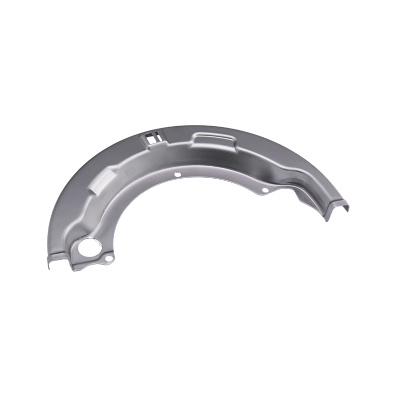
Heavy truck stamping parts
Our Heavy truck stamping parts are precision-manuf...
-
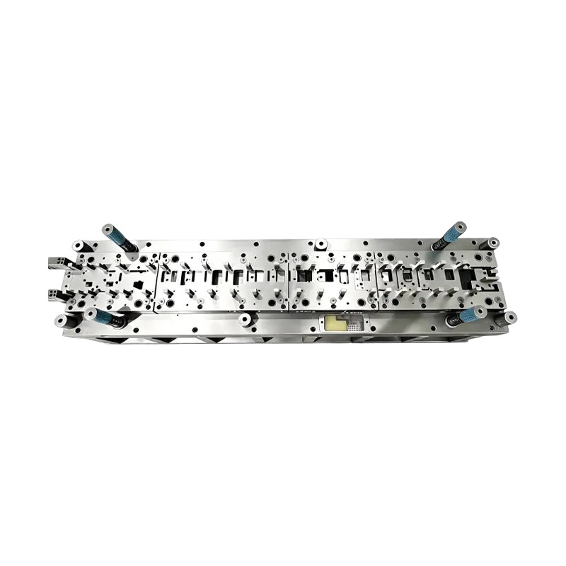
Long-Stroke Multi-Stage Progressive Die Automatic Strip Feed Progressive Die Long Travel Follow on Stamping Tool for Sheet Metal Hardware Press Moulding
Long-Stroke Multi-Stage Progressive DieOur custom ...
-
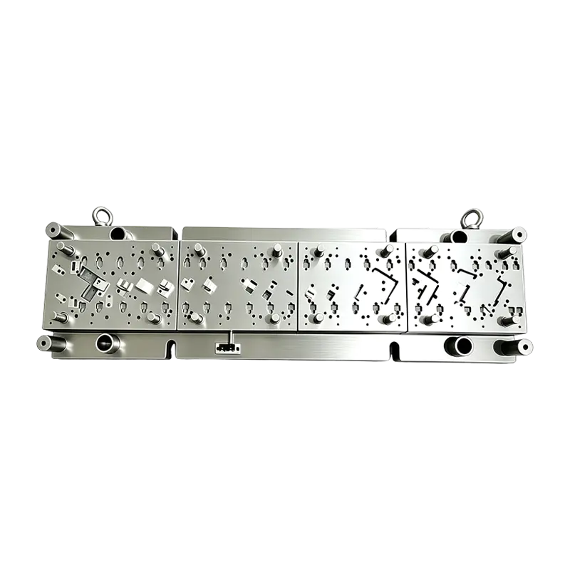
High Speed Progressive Stamping Die Sheet Metal Follow on Press Tool
Multi-operation Metal Stamping Tool for Continuous...
-
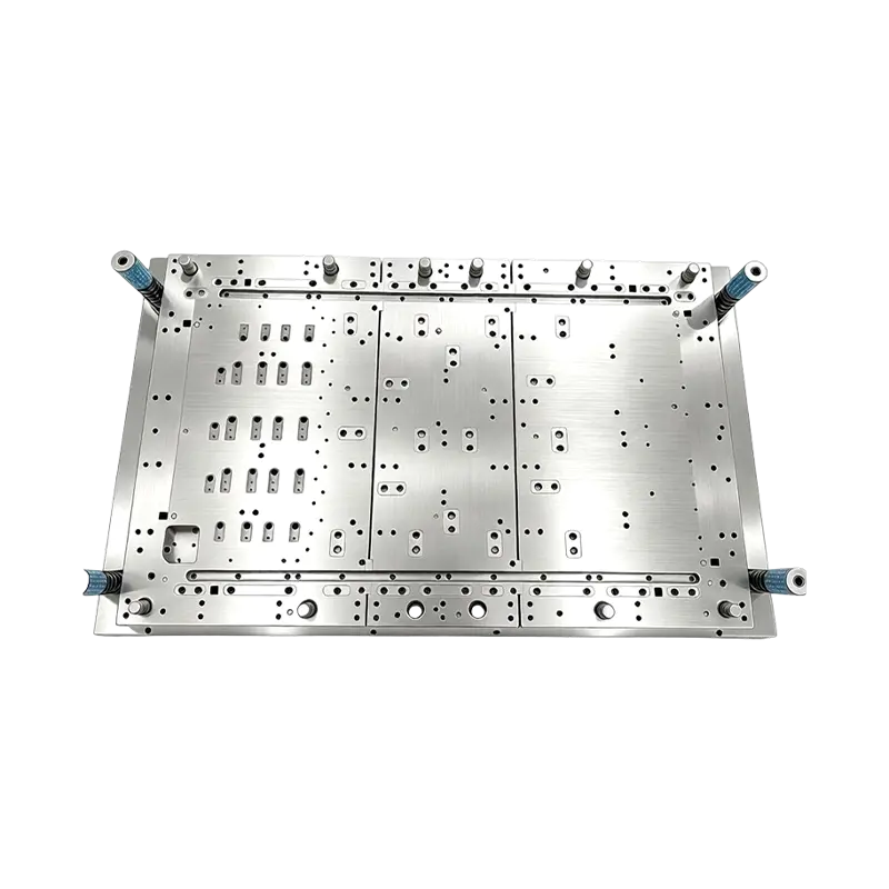
Multi-Station Progressive Stamping Die with Carbide Inserts Custom Multi Station Progressive Stamping Die Carbide Insert Metal Stamping Mold Tool for Equipment Appliances Device Hardware
High Speed Metal Stamping Tool for Precise Equipme...
-
Progressive Stamping Die for Connector & Terminal Parts High Speed Progressive Stamping Die Precision Metal Hardware Stamping Tool mold for Connector Terminal Parts Automotive Components
Progressive Stamping Die for Connector & Termi...
- E-mail us: [email protected]
- Call us: +86-139 1308 8972

Industry News
Home / News / Industry News / Draw Ratio & Blank Holder Force in Deep Drawing: Preventing Wrinkling and Cracking
Draw Ratio & Blank Holder Force in Deep Drawing: Preventing Wrinkling and Cracking
2026-05-20
Two failure modes bracket every deep drawing operation: wrinkling and cracking. They sit on opposite sides of the same process window, and every parameter adjustment that moves you away from one moves you toward the other. Draw ratio and blank holder force are the two levers that define where that window sits and how wide it is. Understanding how they interact — and why — is the foundation of defect prevention in deep drawing.
Content
- 1 Draw Ratio: The Primary Measure of Deformation Severity
- 2 What Happens When Draw Ratio Exceeds the Limit
- 3 Blank Holder Force: Balancing Two Competing Risks
- 4 Variable Blank Holder Force: A More Precise Approach
- 5 Wrinkling: Causes, Types, and Corrections
- 6 Cracking: Causes, Locations, and Corrections
- 7 The Role of Blank Size and Shape in Defect Prevention
- 8 Connecting Defect Prevention to Production Quality
Draw Ratio: The Primary Measure of Deformation Severity
Draw ratio (DR) is the ratio of the blank diameter to the punch diameter. For a 200 mm blank drawn over a 100 mm punch, the draw ratio is 2.0. This number describes how much the blank must contract circumferentially to transform from a flat circle into a cup — and therefore how much compressive stress the flange must carry during the draw stroke.
The limiting draw ratio (LDR) is the maximum draw ratio a given material can sustain in a single drawing pass without the cup wall fracturing near the punch nose. For most low-carbon steels with favorable r-values, the LDR falls between 2.0 and 2.3. For aluminum alloys, it is typically 1.8 to 2.0. For stainless steels, it ranges from 1.9 to 2.2 depending on grade and temper.
The LDR is not a fixed material constant — it shifts with process conditions. Better lubrication raises the LDR by reducing friction-driven wall stress. A larger die entry radius raises it by reducing bending resistance at the die lip. Higher blank holder force lowers it by adding friction load that the cup wall must also carry. The practical implication is that the LDR is a system property, not just a material property, and it must be evaluated in the context of the full tool and process design.
| Material | Typical LDR Range | Key Influencing Factor |
|---|---|---|
| IF steel (high r-value) | 2.1 – 2.3 | High normal anisotropy (r̄ > 1.5) |
| Low-carbon steel (DC01/DC04) | 1.9 – 2.2 | Standard forming grade |
| Stainless steel (304) | 1.9 – 2.1 | Rapid work hardening |
| Aluminum (1xxx/3xxx series) | 1.8 – 2.0 | Low r-value (<1.0) |
| Copper / brass | 2.0 – 2.2 | High ductility, moderate r-value |
What Happens When Draw Ratio Exceeds the Limit
When the draw ratio exceeds the LDR, the cup wall cannot transmit the force needed to draw the remaining flange material into the die without rupturing. Fracture typically initiates at the punch nose radius — the point of maximum wall thinning — and propagates rapidly around the circumference. In production, this appears as a clean tear at the base of the cup wall, often called a "punch-through" failure.
The path back from this failure mode is not always to reduce the blank size. Sometimes, improving lubrication, increasing die entry radius, or reducing binder force (within wrinkling limits) can raise the effective LDR enough to bring the existing blank size within reach. If none of those adjustments are sufficient, a multi-stage draw reduction is the correct engineering response. The multi-stage deep drawing die systems used in automotive EV component production are specifically designed to sequence draw ratios across stations so that no single operation approaches the LDR boundary.
Blank Holder Force: Balancing Two Competing Risks
Blank holder force (BHF) — also called binder force or blank holding pressure — is the clamping force applied to the flange of the blank throughout the drawing stroke. Its role is to prevent the flange from buckling under circumferential compressive stress, which is the root cause of wrinkling. However, BHF also increases the friction the blank must overcome as it slides inward, which adds to the tensile stress in the cup wall and can cause cracking if set too high.
This is the central tension of blank holder design: too little force produces wrinkling; too much produces cracking. The correct value lies between these two limits, and the gap between them — the process window — narrows as draw ratio increases, material thickness decreases, or lubrication quality deteriorates.
A commonly used approximation for the initial blank holder pressure is 1.5% of the material's yield strength, applied over the contact area between the blank holder and the flange. For the first draw of a cylindrical cup, the total BHF can also be estimated as roughly 25% of the drawing force. These are starting points; actual production settings require verification through tryout and adjustment based on part condition — wrinkle presence indicates the need for higher BHF, while wall fracture indicates the need for lower BHF or improved lubrication.
Variable Blank Holder Force: A More Precise Approach
Fixed blank holder force is a useful starting approximation, but it is not optimal throughout the entire draw stroke. At the beginning of the stroke, the flange area is large and the risk of wrinkling is highest — this is where BHF should be at its maximum. As the stroke progresses and the flange diameter decreases, the compressive stress in the flange diminishes, and the BHF requirement falls. Maintaining high BHF through the end of the stroke adds unnecessary friction load to the cup wall, increasing fracture risk without providing any additional wrinkling protection.
Variable BHF systems — typically hydraulic or servo-controlled cushions — apply a time-varying force profile synchronized with punch position. The profile begins at high force, reduces through the mid-stroke, and may increase again slightly near the end to control springback. Research consistently shows that variable BHF widens the effective process window compared to fixed BHF, allowing deeper draws and thinner blanks that would fracture under a constant high-force setting.
Numerically controlled (NC) die cushions take this a step further by applying different pressures at different zones around the blank perimeter — addressing the asymmetric flow resistance inherent in non-round part shapes. This approach is particularly relevant for wheel hub and structural chassis deep drawing dies where perimeter geometry varies significantly.
Wrinkling: Causes, Types, and Corrections
Wrinkling occurs when circumferential compressive stress in the blank exceeds the material's buckling resistance. It appears in two distinct locations, each with a different cause and a different correction strategy.
Flange wrinkling is the most common type. As the blank is drawn inward, its circumference must decrease — material that was distributed around a large circle must compress into a smaller one. If blank holder pressure is insufficient to suppress the out-of-plane buckling that results, the flange develops radial wrinkles that are then pulled into the die cavity and appear as wavy folds on the cup wall. The correction is higher BHF, better binder contact (ensuring the binder is flat and parallel to the flange), or draw beads that add resistance to material flow and increase radial tension in the flange.
Wall wrinkling appears on the vertical wall of the cup, independent of the flange. It is caused by excessive circumferential compression in the unsupported wall between the punch and die, and is more common in thin materials and large draw ratios. Wall wrinkling cannot be corrected by blank holder force alone — it requires die clearance reduction, punch radius adjustment, or a reduction in the draw ratio through an additional drawing stage.
- Insufficient blank holder force — the most frequent wrinkling cause; flange lifts between the binder and die face, allowing circumferential buckling.
- Excessive die entry radius — creates an unsupported span where the blank transitions from flange to wall, giving the material room to buckle before it is captured.
- Oversized working clearance — leaves too much radial play for the wall material, allowing lateral buckling during the stroke.
- Blank geometry mismatch — excess material in specific sectors of a non-round blank creates localized compressive stress concentrations that buckle before the rest of the blank has formed.
- Inadequate lubrication uniformity — uneven lubrication creates variable flow resistance around the perimeter, causing some sectors to feed faster than others and accumulate compressive stress.
Cracking: Causes, Locations, and Corrections
Cracking in deep drawing is a tensile failure. It occurs when the stress in the cup wall — carrying the load of drawing the remaining flange into the die — exceeds the material's tensile strength at the weakest cross-section. That weakest section is almost always at the punch nose radius, where bending reduces thickness and where tensile stress is highest.
The factors that drive cracking upward are the same factors that worsen any other tensile failure: higher draw ratio, higher blank holder force, greater friction at the die radius or binder surface, smaller die entry radius (which increases bending resistance), and material with low ductility or low n-value. Any one of these factors, pushed too far, can fracture a cup that otherwise forms correctly.
Corrections follow from the causes. Reducing BHF within the wrinkling limit is the fastest adjustment available during tryout. Improving lubrication — particularly at the die entry radius — reduces friction-driven wall stress without changing any tooling. Increasing die entry radius reduces bending resistance at the die lip. If none of these adjustments is sufficient, the draw ratio must be reduced, either by reducing the blank size (accepting a shorter cup) or by adding a drawing stage to distribute the deformation. The economic implications of adding drawing stages versus accepting yield loss to cracking depend on production volume and part cost — a decision that must be made in context.
| Defect | Root Cause | Primary Correction | Secondary Correction |
|---|---|---|---|
| Flange wrinkles | Insufficient BHF | Increase blank holder force | Add draw beads; check binder flatness |
| Wall wrinkles | Excess clearance or high DR | Reduce working clearance | Add redraw stage; reduce blank size |
| Punch-nose fracture | Excessive wall stress | Reduce BHF; improve lubrication | Increase die entry radius; add draw stage |
| Thinning without fracture | High DR near LDR limit | Optimize lubrication uniformity | Reduce draw ratio per stage |
| Earing (uneven cup rim) | Planar anisotropy (Δr) | Rotate blank orientation | Select material with lower Δr |
The Role of Blank Size and Shape in Defect Prevention
Blank geometry is often treated as a fixed input — the blank diameter is calculated from the surface area of the finished part, and that is that. In practice, blank shape optimization is a powerful defect prevention tool, particularly for non-round parts.
For round cups, a circular blank is correct. For rectangular or irregular parts, a blank that perfectly matches the developed surface area of the finished part will have excess material in some sectors and insufficient material in others relative to the die perimeter. That imbalance creates uneven flow resistance, which creates uneven stress distribution, which creates localized wrinkling or fracture at predictable locations.
Blank shape optimization — adjusting the perimeter of a non-round blank so that each sector feeds at the same rate — can eliminate entire defect categories without changing any tooling. FEA simulation is the standard tool for this optimization, iterating the blank outline until the forming limit diagram shows uniform safety margins around the entire part perimeter. The resulting blank is rarely a simple rectangle or oval; it has notches, reliefs, and contours tuned to the specific die geometry it will be drawn through.
Connecting Defect Prevention to Production Quality
Wrinkling and cracking are the visible symptoms of a process operating outside its window. Diagnosing which symptom appears — and where — points directly to which parameter is out of range. A crack at the punch nose implicates wall stress: BHF too high, lubrication failing, or draw ratio exceeding the material's LDR. A wrinkle on the flange implicates compressive stress control: BHF too low, binder contact uneven, or draw bead insufficient. A wrinkle on the wall implicates die clearance or draw ratio, not BHF.
Treating each defect type as a diagnostic signal — rather than as a generic quality failure — allows targeted corrective action rather than trial-and-error parameter adjustments. This structured approach is what separates predictable, high-yield deep drawing production from chronic tryout cycles.
For complex parts combining deep draws with progressive die features, the same diagnostic logic applies at each station. Progressive deep drawing dies for automotive structural parts must control draw ratio and blank holder conditions independently at each stage — a discipline that, when executed correctly, produces defect-free parts at high production rates across the full range of automotive stamping part geometries and material grades.
Previous Post
Automotive Seat Stamping Parts: High-Precision Manufacturing, Load Bearing & Material Selection
Next Post
Deep Drawing Die Design: Punch, Die, Clearance & Multi-Stage Reduction Guide
Our Products.
Start Your Business with an OEM Manufacturer Right Here!

Provide global customers with complete turn-key solutions
through
innovation!
QUICK LINKS
CONTACT INFO.
-
 +86-139 1308 8972
 -

-
 No. 118 Yexin Road, Wujiang Economic Development Zone, Suzhou, China
Copyright © Suzhou Shuangqisi Mold Equipment Co., Ltd. All Rights Reserved. Custom Stamping Die Metal Stamping Die Manufacturers
