 English
 Español
 Deutsch
-
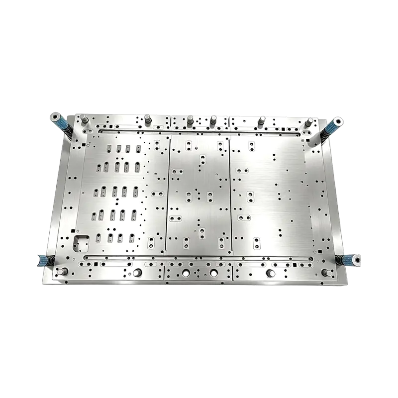
Multi-Station Progressive Stamping Die with Carbide Inserts Custom Multi Station Progressive Stamping Die Carbide Insert Metal Stamping Mold Tool for Equipment Appliances Device Hardware
High Speed Metal Stamping Tool for Precise Equipme...
-
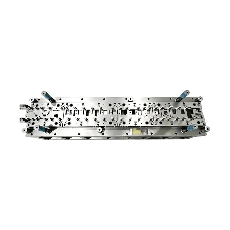
Long-Stroke Multi-Stage Progressive Die Automatic Strip Feed Progressive Die Long Travel Follow on Stamping Tool for Sheet Metal Hardware Press Moulding
Long-Stroke Multi-Stage Progressive DieOur custom ...
-
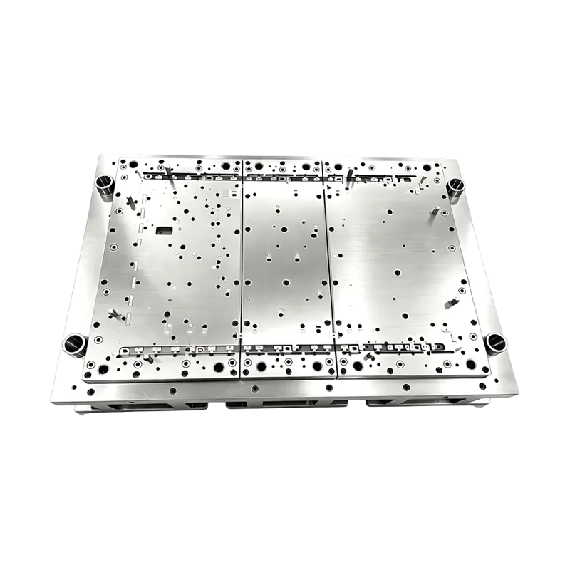
High Precision Stamping Die Multi Station Hardware Progressive Mold Tooling
Precision Metal Stamping Tool for Automotive &...
-

Deep drawing mold for front and rear wheels of two-wheeled electric vehicles
This Deep drawing mold for front and rear wheels o...
-
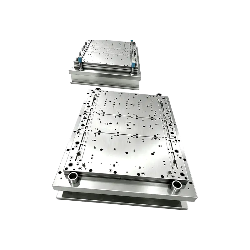
Progressive Stamping Die for Connector & Terminal Parts High Speed Progressive Stamping Die Precision Metal Hardware Stamping Tool mold for Connector Terminal Parts Automotive Components
Progressive Stamping Die for Connector & Termi...
-
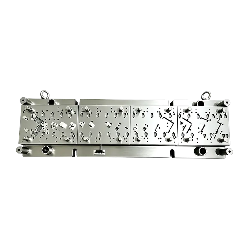
High Speed Progressive Stamping Die Sheet Metal Follow on Press Tool
Multi-operation Metal Stamping Tool for Continuous...
- E-mail us: [email protected]
- Call us: +86-139 1308 8972

Industry News
Home / News / Industry News / Deep Drawing Die Design: Punch, Die, Clearance & Multi-Stage Reduction Guide
Deep Drawing Die Design: Punch, Die, Clearance & Multi-Stage Reduction Guide
2026-05-20
Sheet metal that enters a die as a flat blank and exits as a seamless, hollow component — that transformation depends entirely on how well the die is designed. Deep drawing die design is not a single decision but a chain of engineering choices, each of which either opens or closes the window in which successful forming can occur. A poorly specified punch radius, an undersized blank holder, or a miscalculated clearance can collapse that window completely, producing cracked or wrinkled scrap at high volume. The sections below walk through every major design variable and explain what each one controls.
Content
- 1 What Deep Drawing Die Design Actually Controls
- 2 Punch and Die Geometry: Where the Part Shape Comes From
- 3 Working Clearance Between Punch and Die
- 4 Material Selection and Its Influence on Die Design
- 5 Multi-Stage Draw Reduction: When One Operation Is Not Enough
- 6 Draw Beads and Binder Pressure: Fine-Tuning Material Flow
- 7 Lubrication and Die Surface Finish
- 8 Tool Steel Selection and Die Durability
- 9 Simulation Before Steel: Finite Element Analysis in Die Design
- 10 Summary: The Design Variables That Matter Most
What Deep Drawing Die Design Actually Controls
A deep drawing tool set has three primary members: the punch, the die, and the blank holder. The punch pushes the flat blank into the die cavity. The die defines the outer geometry of the finished part. The blank holder presses against the flange of the blank to regulate how much material feeds into the cavity during the stroke.
Each member must be designed in relation to the others. Punch diameter establishes the inner diameter of the drawn cup; die diameter is larger by the amount of the working clearance. The blank holder sits between the two, maintaining contact pressure on the flange throughout the stroke. When the relationships among these three components are correct, the metal flows inward and downward without wrinkling on the flange or fracturing at the punch nose. When any relationship is wrong, one of those two failure modes appears immediately.
For high-volume production, automotive-grade deep drawing die sets add further requirements: longer tool life, tight part-to-part consistency, and compatibility with automated transfer systems. Those requirements intensify the importance of every design decision described below.
Punch and Die Geometry: Where the Part Shape Comes From
The punch nose radius and the die entry radius are the two most consequential geometric parameters in deep drawing die design. Both control how the metal bends as it transitions from the flat blank into the drawn wall.
Punch nose radius is typically set between four and eight times material thickness for standard steels. A radius that is too small concentrates tensile stress at the bend, promoting thinning and eventual fracture. A radius that is too large allows the metal to buckle before it is captured by the die wall, producing wall wrinkles.
Die entry radius — sometimes called the die corner radius — governs the resistance the blank encounters as it is drawn over the die edge. A well-polished, appropriately sized die radius reduces friction and allows material to flow smoothly into the cavity. Standard practice sets this radius at four to ten times material thickness, depending on the draw ratio and material ductility. Undersized radii increase the risk of tearing; oversized radii in thin materials create unsupported spans that buckle into wrinkles.
For parts with square or rectangular cross-sections, corner radii require individual attention. Corners concentrate compressive stress during forming, and generous corner radii — typically larger than for equivalent round parts — allow deeper draws in a single operation without corner wrinkling.
Working Clearance Between Punch and Die
Clearance is the radial gap between the punch and the die wall. During drawing, the metal must pass through this gap, and it typically thickens slightly as it flows inward. The clearance must accommodate that thickening without squeezing the metal so tightly that friction rises to destructive levels, and without leaving so much space that the metal buckles laterally into wall wrinkles.
For most low-carbon steels, a working clearance of 1.07 to 1.15 times material thickness per side is the accepted starting range. Harder or thicker materials may require clearance at the upper end of this range. Thinner materials and tighter tolerances on wall thickness push the design toward the lower end. Progressive die systems for multi-station automotive progressive deep drawing dies apply the same logic at each successive station, with clearance typically tightening as the cup diameter reduces and wall uniformity becomes more critical.
Material Selection and Its Influence on Die Design
The die designer cannot choose the part material, but material properties determine which design parameters are feasible. Two sheet-metal properties are especially relevant: the strain-hardening exponent (n-value) and the plastic strain ratio (r-value, also called the Lankford coefficient).
A high n-value means the material hardens rapidly as it stretches, distributing deformation more evenly across the blank. This allows more aggressive draw ratios before fracture. A high r-value means the material resists thinning in the through-thickness direction and flows preferentially in the plane of the sheet — exactly what deep drawing requires. Materials with high r-values can be drawn to larger depth-to-diameter ratios before the punch-nose fracture limit is reached.
In practical terms, an interstitial-free (IF) steel with r-values above 1.8 permits die designs with deeper single-draw depths and larger blank-to-punch diameter ratios than a conventional low-carbon steel with r-values near 1.0. Aluminum alloys generally have r-values below 1.0, which means die designs for aluminum must rely more on multi-stage draw reductions and more careful blank holder control to achieve the same cup depth. The same principles apply when designing precision automotive stamping components where tight dimensional tolerances compound material variability challenges.
Multi-Stage Draw Reduction: When One Operation Is Not Enough
When the required depth-to-diameter ratio of the finished part exceeds what a single draw can achieve safely — typically a draw ratio above 2.0 to 2.2 for most steels — the design must incorporate multiple drawing stages. Each stage reduces the cup diameter while increasing its height, and each stage has its own punch, die, and blank holder.
The first draw takes the flat blank to the maximum draw ratio the material permits. Subsequent redraws operate on the already-formed cup, and they can achieve draw ratios of 1.2 to 1.4 per stage because the metal at the flange is already partially work-hardened and carries less risk of severe wrinkling. Annealing between stages may be required for materials that work-harden rapidly, to restore ductility before the next reduction.
| Draw Stage | Typical Max Draw Ratio | Notes |
|---|---|---|
| First draw | 1.8 – 2.2 | Depends on r-value and blank thickness |
| Second draw (redraw) | 1.2 – 1.4 | Lower risk due to prior work-hardening |
| Third draw and beyond | 1.1 – 1.3 | Anneal may be required between stages |
Multi-stage designs add tooling cost and press time, but they are often the only path to the required part geometry. The economic comparison between single-stage and multi-stage approaches is closely tied to production volume — a factor explored in more detail in the article on cost differences between metal stamping and deep drawing part products.
Draw Beads and Binder Pressure: Fine-Tuning Material Flow
Draw beads are raised ridges machined into the binder (blank holder) surface. As the blank slides over them during the draw stroke, they impose bending and unbending deformation that creates additional resistance to material flow. By varying the height, width, and position of draw beads around the blank perimeter, the die designer can control how much material enters the die cavity at each point — redirecting flow away from areas prone to tearing and toward areas that might otherwise wrinkle.
Draw bead positioning is especially important for non-axisymmetric parts, such as automotive body panels, where different sections of the blank perimeter need very different flow resistance. Parts with large flat areas surrounded by deep draws often require draw beads to prevent the flat areas from developing surface distortion under the binder.
Binder pressure complements draw bead design. The binder must apply enough force to prevent the flange from buckling into wrinkles, but not so much that it blocks the flow of material into the cavity — which would increase tensile stress in the cup wall to the point of fracture. The correct binder pressure therefore lies within a process window whose boundaries are defined by the wrinkling limit below and the fracture limit above. The next article in this series addresses how draw ratio and blank holder force interact to define and control that window.
Lubrication and Die Surface Finish
Friction at the die entry radius and blank holder interface has a direct effect on the tensile stress carried by the cup wall. Higher friction means higher wall stress — which moves the process closer to the fracture limit. Effective lubrication reduces that stress and widens the process window.
Die surface finish interacts with lubrication. A polished die radius with surface roughness below Ra 0.4 µm allows lubricant to form a consistent film, reducing friction variability. Rough or scratched surfaces trap lubricant unevenly and introduce localized stress concentrations that can initiate fracture at lower-than-expected wall stresses.
Lubricant selection depends on the material being drawn. Low-carbon steels tolerate a wide range of lubricants, from light drawing oils to heavy EP (extreme-pressure) compounds. Aluminum alloys require lubricants that do not react with the metal surface, as reactive compounds can cause galling and surface scoring. Stainless steels — which work-harden rapidly — often require chlorinated lubricants to manage the high interface pressures generated during drawing.
Tool Steel Selection and Die Durability
Die life in deep drawing is limited by abrasive wear at the die entry radius and by galling on the binder surface. Both mechanisms accelerate when binder pressure is high, lubricant film breaks down, or the blank material contains abrasive inclusions.
Standard die materials for medium-volume production include D2 tool steel (approximately 60–62 HRC after hardening) and DC53, which offers better toughness at similar hardness. High-volume automotive production often demands tungsten carbide inserts at the die entry radius, where wear rates are highest. Surface coatings — titanium nitride (TiN), titanium carbonitride (TiCN), or diamond-like carbon (DLC) — extend service life further by reducing the coefficient of friction at the tool-blank interface.
For high-precision stamping die sets targeting automotive or EV component tolerances, tool steel selection and heat treatment specification are as critical as the geometric design parameters described above. A dimensionally perfect die machined from improperly heat-treated steel will fail long before its design life.
Simulation Before Steel: Finite Element Analysis in Die Design
Modern deep drawing die design relies heavily on finite element analysis (FEA) to predict forming outcomes before any metal is cut. FEA simulations model the blank as a mesh of deformable elements, apply the punch stroke incrementally, and calculate stress, strain, and thickness distribution at every point in the blank throughout the stroke.
The output of a well-calibrated simulation includes a forming limit diagram (FLD) overlay, which shows whether any region of the blank is approaching the fracture or wrinkling boundary. If the simulation predicts failures, the designer can adjust punch radius, die radius, binder pressure, draw bead geometry, or blank shape — iterating in software rather than in steel. This process compresses tryout time significantly and reduces the number of physical tool modifications required before the die produces acceptable parts.
The quality of the simulation depends on accurate material card data — specifically the yield surface description, r-values, n-value, and flow stress curve for the specific material coil to be used in production. Generic material data produces plausible but unreliable predictions; material-specific data from tensile testing and FLD testing produces predictions that translate directly to press behavior.
Summary: The Design Variables That Matter Most
Deep drawing die design resolves to a small number of variables, each of which must be set within a range that depends on the others. Punch and die radii determine bend severity at the transitions. Working clearance accommodates metal thickening without generating destructive friction. Draw ratio sets the upper limit of deformation in a single stage. Binder pressure and draw beads control material flow around the blank perimeter. Lubrication and surface finish determine how much of the allowable binder pressure actually reaches the blank. Tool steel and coating selection govern how long the die maintains those carefully established conditions.
No single variable can be optimized in isolation. A change to the die entry radius changes the optimal binder pressure. A change in material grade changes the feasible draw ratio. This interdependence is why deep drawing die design demands a systematic approach — and why getting it right, from simulation through tryout, produces parts that meet demanding structural and dimensional requirements for wheel and chassis applications consistently across millions of production cycles.
Previous Post
Draw Ratio & Blank Holder Force in Deep Drawing: Preventing Wrinkling and Cracking
Next Post
Car Seat Stamping Parts: Quality & Fit Guide
Our Products.
Start Your Business with an OEM Manufacturer Right Here!

Provide global customers with complete turn-key solutions
through
innovation!
QUICK LINKS
CONTACT INFO.
-
 +86-139 1308 8972
 -

-
 No. 118 Yexin Road, Wujiang Economic Development Zone, Suzhou, China
Copyright © Suzhou Shuangqisi Mold Equipment Co., Ltd. All Rights Reserved. Custom Stamping Die Metal Stamping Die Manufacturers
