 English
 Español
 Deutsch
-
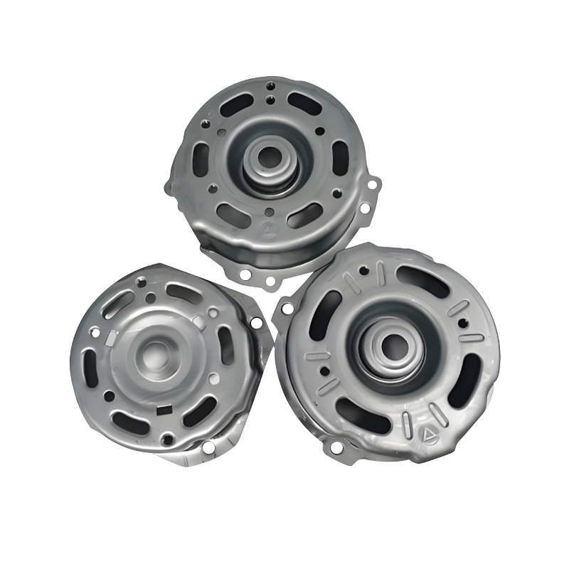
Automotive motor housing stamping parts
Automotive motor housing stamping parts are core c...
-
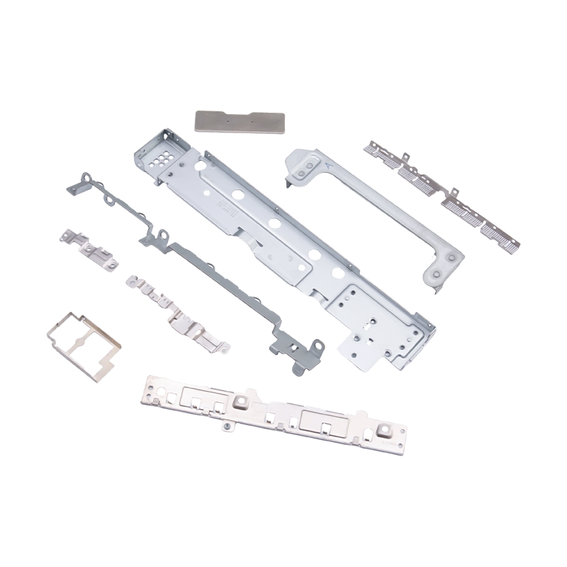
Small stamped parts for laptops and mobile phones
As essential internal components for modern portab...
-

Deep drawing mold for front and rear wheels of two-wheeled electric vehicles
This Deep drawing mold for front and rear wheels o...
-
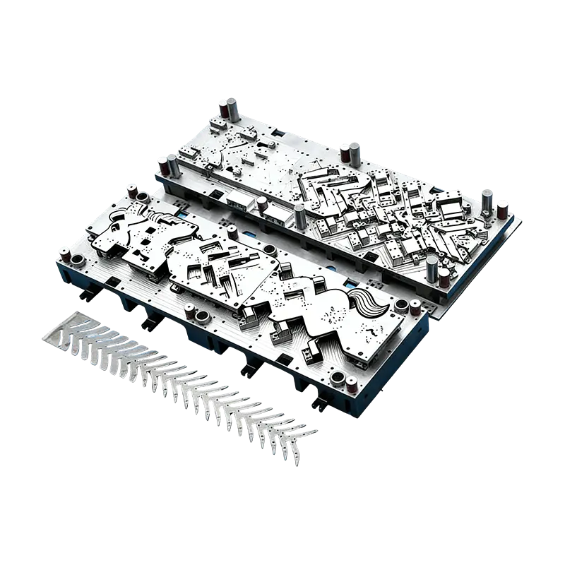
Progressive molds for automotive parts
This Continuous mold for automotive motor housing ...
-
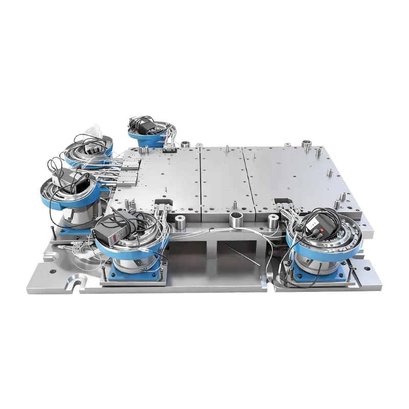
Automatic riveting mold for large computer machine base
This Automatic Riveting Mold for Large Computer Ma...
- E-mail us: [email protected]
- Call us: +86-139 1308 8972
Industry News
Home / News / Industry News / What's the Difference Between Traditional and Simulation-Optimized Automotive Stamping Dies?
What's the Difference Between Traditional and Simulation-Optimized Automotive Stamping Dies?
2026-03-02
Content
- 1 Why the Gap Between Traditional and Simulation-Optimized Dies Matters Now
- 2 How Traditional Automotive Stamping Die Development Actually Works
- 3 What Simulation-Optimized Die Design Changes in the Development Process
- 4 Deep Drawing Dies for EV Components: Where Simulation Becomes Essential
- 5 Head-to-Head Comparison: Traditional vs. Simulation-Optimized Stamping Die Development
- 6 Intelligent Monitoring Integration and the Role of Modular Die Structures
- 7 Practical Guidance for Engineering Teams Evaluating the Transition
Why the Gap Between Traditional and Simulation-Optimized Dies Matters Now
Automotive stamping dies have always been among the most technically demanding tooling investments in vehicle manufacturing. A single set of dies for a body panel can represent hundreds of thousands of dollars in engineering, machining, and tryout time—and the consequences of getting the design wrong are measured not just in rework cost but in delayed production launches, increased scrap rates, and compromised part quality that propagates through downstream assembly operations. For decades, die design relied on the accumulated empirical knowledge of experienced toolmakers: iterative physical tryouts, manual adjustments to blank holder force and draw bead geometry, and progressive refinement through trial and error until the die produced acceptable parts consistently.
The shift toward simulation-optimized automotive stamping dies did not happen overnight, but its pace has accelerated sharply as vehicle programs have become simultaneously more complex and more time-compressed. Electric vehicles in particular have introduced new material challenges—magnesium-aluminum alloy battery casings, ultra-high-strength steel structural components, and complex deep-drawn geometries that push forming limits—that the traditional empirical approach cannot address reliably within the compressed development timelines the market demands. Understanding the concrete differences between traditional and simulation-optimized die design and production is essential for engineering teams evaluating their tooling development processes in 2025 and beyond.
How Traditional Automotive Stamping Die Development Actually Works
Traditional automotive stamping die development begins with part geometry and material specification, from which an experienced die designer constructs a die concept based on established design rules and pattern-matching to previous similar parts. The punch, die, blank holder, and die set geometry are defined through a combination of handbook formulas, proprietary design guidelines, and designer judgment. Blank size is estimated using area-based methods or simplified geometric unfolding, and draw bead positions and restraint forces are selected based on general experience with comparable panel shapes rather than analysis of the specific stress state in the current part.
The physical tryout phase is where the traditional process either validates or exposes the limitations of this approach. When the initial die produces parts with wrinkling in low-stress regions, cracking at tight radii, excessive material thinning at critical structural locations, or springback that pushes formed geometry outside the ±0.02mm tolerance band required for precision body panel assembly, the response is physical intervention: adjusting blank holder force through shim additions, modifying draw bead geometry by welding and regrinding, changing surface treatment in high-friction zones, or cutting back die surfaces to alter metal flow patterns. Each intervention requires a new tryout run, and complex panels may require dozens of iterations before the die produces consistently acceptable parts.
The cost implications of this approach are substantial. Physical tryout time on a large transfer press or progressive die line is expensive, and the engineering labor required to diagnose defects, design interventions, and execute modifications accumulates quickly on challenging panels. More significantly, the empirical approach provides no guarantee of convergence—some die designs based purely on experience reach a local optimum that cannot be improved without fundamental redesign, a situation that may not become apparent until significant investment has already been made in physical tooling.
What Simulation-Optimized Die Design Changes in the Development Process
Simulation-optimized automotive stamping die development replaces much of the physical trial-and-error cycle with virtual forming analysis conducted before any metal is cut. Finite element analysis (FEA) software models the complete forming process—from blank contact with the blank holder through full draw depth—computing the stress, strain, thickness distribution, and springback behavior of the sheet metal under the applied tooling geometry and process conditions. The simulation output identifies potential defect locations: regions approaching the forming limit curve where cracking risk is elevated, zones of compressive stress accumulation where wrinkling will occur, and areas of excessive thinning that would compromise structural performance or surface quality.
Critically, simulation enables parametric optimization that would be practically impossible through physical tryout. Blank holder force can be varied across its full feasible range in minutes of computation time to find the value that simultaneously suppresses wrinkling and avoids cracking—the opposing failure modes that make blank holder force calibration so challenging in traditional die development. Draw bead geometry, position, and restraint force can be optimized for each section of the blank perimeter independently, accounting for the direction-dependent flow resistance needed to manage metal distribution in complex asymmetric panel geometries. Surface treatment selection—including the ultra-smooth Ra ≤ 0.05μm finishes required in deep drawing zones—can be evaluated through friction coefficient sensitivity studies that quantify how surface quality improvements affect forming outcomes before committing to the machining and finishing operations that achieve them.
Deep Drawing Dies for EV Components: Where Simulation Becomes Essential
The electric vehicle transition has introduced forming challenges that make simulation not merely advantageous but practically necessary. Deep drawing dies for EV-specific components—particularly magnesium-aluminum alloy battery casings with deep drawing ratios exceeding 2.5:1—operate at the boundary of what the material can sustain without failure. The forming limit behavior of aluminum alloys is fundamentally different from the mild and high-strength steels that traditional automotive stamping die development accumulated experience around: aluminum exhibits lower formability, stronger anisotropy effects, and greater sensitivity to strain rate and temperature than conventional body panel steel grades.
Simulation tools calibrated with accurate material property data—including forming limit curves, anisotropy coefficients, and flow stress curves determined from physical material characterization testing—can predict whether a proposed die geometry will successfully form an aluminum battery casing without cracking at the punch radius or wrinkling in the flange, before any tooling investment is made. This predictive capability is especially valuable for deep drawing ratios above 2.5:1, where the process window between wrinkling and cracking failure modes narrows to the point that empirical adjustment is unlikely to find a stable operating condition without systematic computational guidance.
Material thinning prediction is another critical simulation output for EV deep drawing dies. Battery casings and structural EV components have defined minimum wall thickness requirements driven by structural analysis and safety standards. Simulation allows die designers to verify that thinning in the most severely stretched regions remains within allowable limits across the full range of production variation—material property scatter, blank thickness tolerance, lubrication condition variation—rather than only at the nominal design point that physical tryout represents.
Head-to-Head Comparison: Traditional vs. Simulation-Optimized Stamping Die Development
The practical differences between the two approaches are best understood across the key dimensions that drive die program cost, timing, and quality outcomes:
| Development Dimension | Traditional Approach | Simulation-Optimized Approach |
| Defect detection timing | Physical tryout, post-machining | Virtual analysis, pre-machining |
| Blank holder force optimization | Empirical shim adjustment | Parametric FEA sweep |
| Aluminum/EV material capability | Unreliable above 2.0:1 draw ratio | Validated for ratios exceeding 2.5:1 |
| Springback management | Trial-and-error compensation cuts | Predicted and pre-compensated in CAD |
| Tolerance achievement (±0.02mm) | Multiple tryout iterations required | First-hit capability significantly higher |
| Program timing risk | High, tryout iterations unpredictable | Reduced, major issues resolved virtually |
Intelligent Monitoring Integration and the Role of Modular Die Structures
Simulation optimization does not end when the die design is finalized and machined. Modern automotive stamping dies increasingly integrate intelligent monitoring systems—in-die sensors measuring blank holder force distribution, acoustic emission sensors detecting crack initiation, and vision systems inspecting part geometry at press rate—that provide real-time feedback during production. This monitoring infrastructure allows process engineers to detect drift from the optimized forming conditions that simulation established as the stable operating window, triggering corrective action before defect rates increase rather than after scrap accumulates.
Modular die structures further extend the value of simulation optimization by allowing individual die components—inserts at wear-critical locations, draw bead segments, blank holder sections—to be replaced independently when wear degrades their geometry below the tolerance required to maintain the optimized forming condition. Rather than retiring an entire die set when one region approaches wear-out, modular construction allows targeted replacement of the affected components, preserving the investment in the remaining die structure and maintaining the surface treatment quality—Ra ≤ 0.05μm in critical forming zones—that the simulation-optimized process depends on for consistent friction conditions and part quality.
Practical Guidance for Engineering Teams Evaluating the Transition
Engineering teams considering a transition from traditional to simulation-optimized automotive stamping die development should assess their current process against several practical criteria. The case for simulation investment is strongest when the program includes any of the following characteristics that traditional empirical methods handle poorly:
- Advanced high-strength steel or aluminum alloy materials where forming limit margins are narrow and material property variation has significant impact on defect risk
- Deep drawing dies targeting draw ratios above 2.0:1, particularly for EV battery casings and structural hollow components where material thinning limits are tightly specified
- Body panels with Class A surface requirements where wrinkling or surface deflection defects are cosmetically unacceptable and cannot be tolerated even temporarily during tryout
- Programs with compressed development timelines where extended physical tryout iterations represent unacceptable schedule risk
- High-volume production dies where the amortized cost of simulation investment is negligible relative to the production efficiency gains from a more stable and robust forming process
The investment required to implement simulation-optimized automotive stamping die development encompasses software licensing, material characterization testing to populate accurate simulation material cards, and the engineering skill development needed to interpret simulation results and translate them into actionable die design decisions. These costs are real but are consistently recovered through reductions in physical tryout time, lower scrap rates during production launch, and the elimination of late-stage die modifications that represent some of the most expensive interventions in automotive program development. For facilities producing dies for both traditional body panels and EV-specific lightweight components, simulation capability is not a future aspiration—it is a present competitive requirement.

Previous Post
What Are the Key Differences Between Micro-Stamping and Standard Electronic Parts?
Next Post
How Do Advanced High-Strength Steels Change Automotive Stamping Parts Manufacturing?
Our Products.
Start Your Business with an OEM Manufacturer Right Here!
Provide global customers with complete turn-key solutions
through
innovation!
QUICK LINKS
CONTACT INFO.
-
 +86-139 1308 8972
 -

-
 No. 118 Yexin Road, Wujiang Economic Development Zone, Suzhou, China
Copyright © Suzhou Shuangqisi Mold Equipment Co., Ltd. All Rights Reserved. Custom Stamping Die Metal Stamping Die Manufacturers
