 English
 Español
 Deutsch
-
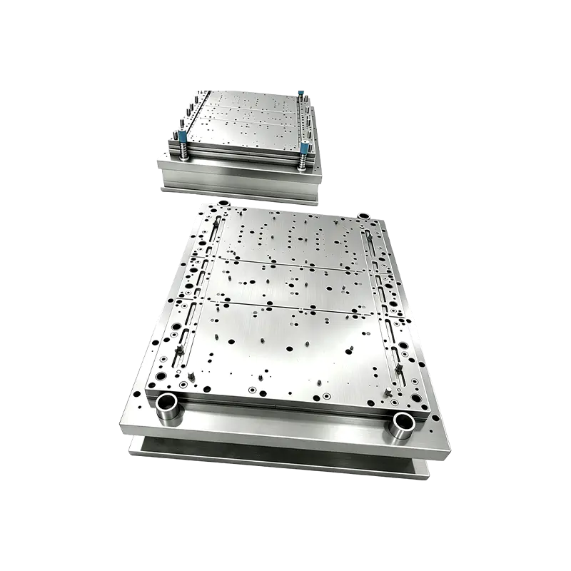
Progressive Stamping Die for Connector & Terminal Parts High Speed Progressive Stamping Die Precision Metal Hardware Stamping Tool mold for Connector Terminal Parts Automotive Components
Progressive Stamping Die for Connector & Termi...
-
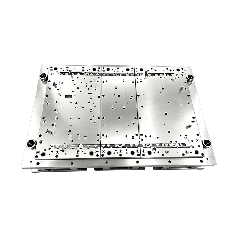
High Precision Stamping Die Multi Station Hardware Progressive Mold Tooling
Precision Metal Stamping Tool for Automotive &...
-
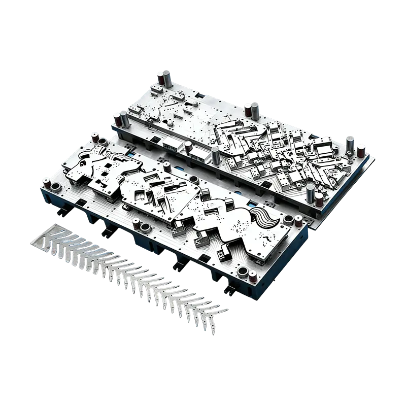
Progressive molds for automotive parts
This Continuous mold for automotive motor housing ...
-
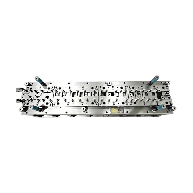
Long-Stroke Multi-Stage Progressive Die Automatic Strip Feed Progressive Die Long Travel Follow on Stamping Tool for Sheet Metal Hardware Press Moulding
Long-Stroke Multi-Stage Progressive DieOur custom ...
-
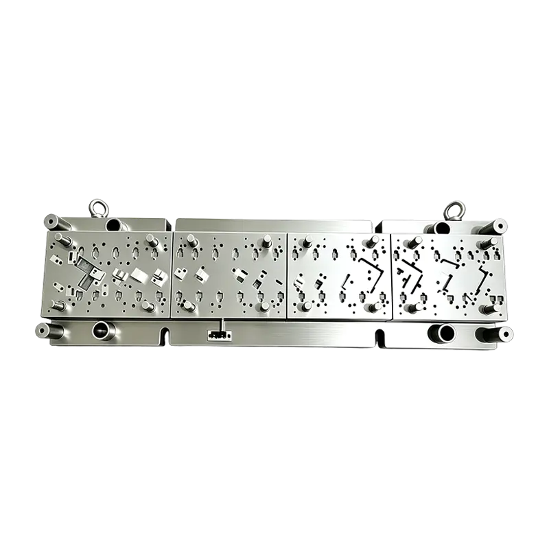
High Speed Progressive Stamping Die Sheet Metal Follow on Press Tool
Multi-operation Metal Stamping Tool for Continuous...
-
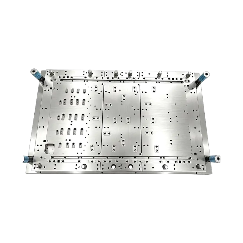
Multi-Station Progressive Stamping Die with Carbide Inserts Custom Multi Station Progressive Stamping Die Carbide Insert Metal Stamping Mold Tool for Equipment Appliances Device Hardware
High Speed Metal Stamping Tool for Precise Equipme...
- E-mail us: [email protected]
- Call us: +86-139 1308 8972

Industry News
Home / News / Industry News / Automotive Part Progressive Stamping: Dies, Tolerances, Costs, and Volume Guide
Automotive Part Progressive Stamping: Dies, Tolerances, Costs, and Volume Guide
2026-10-08
Take a 1.8 mm HSLA 340 seat-bracket. Run it on a 14-station progressive die fed from coil and the piece price typically lands at around 40 percent of what a manual cell of six single-action presses would charge. The progressive line holds hole position inside ±0.08 mm across a full shift with one operator loading coils. The manual cell needs four people to feed blanks and still drifts out of tolerance on the third shift. That gap is the entire argument for progressive stamping on automotive parts — and it only holds when the volume, the strip layout and the tool steel are specified correctly from the start.
The short answer for most automotive programmes:
- Progressive stamping becomes the cheapest route once annual volume clears roughly 150,000 to 200,000 pieces for a bracket-class part, and much lower when several part numbers share one strip.
- Material utilisation — not press speed — is the largest single cost lever. A three percent strip-width reduction usually outperforms a ten percent cycle-time reduction on total cost per part.
- Tolerances accumulate across stations, so hole position, bend angle and flatness must be assigned to specific stations rather than to the finished drawing alone.
- Dies, stamped parts and the feed automation should be engineered as one system. Split them across three suppliers and the tolerance stack is normally the first casualty.
Content
- 1 Where Progressive Stamping Beats the Alternatives
- 2 What Actually Happens Inside a Progressive Die
- 3 Progressive vs Transfer vs Manual: A Side-by-Side Comparison
- 4 Three Hidden Metrics That Decide Line Profitability
- 5 Where Automotive Progressive Stamping Parts Are Used
- 6 Specifying a Progressive Stamping Programme: Seven Steps
- 7 Maintenance, Tolerance Retention and Compliance Records
Where Progressive Stamping Beats the Alternatives
A progressive die performs every operation — piercing, drawing, trimming, forming, flanging and separation — inside a single press stroke, with the strip advancing one pitch per stroke. The part is never handled by a person between operations, which is where the precision and the labour savings both come from. The economics flip depending on three variables: volume, material thickness and how many stations the geometry genuinely requires.
Thin-gauge parts under 3 mm with high annual volume are the classic progressive candidates. Heavier sections above 6 mm, or parts with a deep draw that needs several redraw stations, often favour deep drawing or transfer dies instead — the tooling bill for a 20-station progressive die on a 5 mm floorpan member is hard to justify against a four-slide transfer line.
Strip layout
Pitch, web width and carrier design decide material utilisation before a single station is cut. A 2 mm web reduction across a 300 mm coil is worth more than most press upgrades.
Station count
Each added station raises die cost, maintenance load and press tonnage. Idle stations are sometimes reserved deliberately for a future revision — a cheap hedge against a design change.
Tonnage window
Cutting force peaks at the moment of shear. A die that fits a 250 T press on paper can spike past it on a hard strip, so tonnage margin of 20 to 30 percent is normal practice.
Tool steel grade
Coated carbide or powder-metallurgy steel at the piercing stations extends regrind intervals on high-strength strip, but only when the die shoe and guide pillars are stiff enough to match.
What Actually Happens Inside a Progressive Die
The station sequence carries the engineering. A typical automotive progressive tool opens with a pilot hole and notch station, moves into the first draw or form, adds trimming and piercing as the material work-hardens, then finishes with flanging, restriking and a parting cut that leaves the part on the carrier until the last strike.
Three details decide whether the tool holds tolerance after six months of production. Pilot pins must engage before any cutting station to lock the strip position. The stripper plate must hold the strip flat during the draw, or the panel will spring back unevenly. And the scrap must exit downward through chutes without ever re-entering the strip path — a returning slug is the single most common cause of catastrophic die damage.
On advanced high-strength steels, springback compensation is built into the form stations rather than corrected later. Die builders typically overbend the flange by a calculated angle and then restrike it, because a 590 MPa or 780 MPa strip will not hold a nominal angle on its own. The difference between progressive and transfer metal stamping comes down to how the part is transported between these stations — one relies on the strip carrier, the other on a transfer mechanism — and that choice changes tooling cost, cycle time and the tolerance you can realistically promise.
Progressive vs Transfer vs Manual: A Side-by-Side Comparison
The table below compares three routes for a mid-size automotive structural bracket at roughly 200,000 pieces per year. Figures are typical planning values used for supplier comparison, not quotations.
Criterion
Progressive die
Transfer die
Manual / single-action
Tooling investment
High
Medium
Low
Piece price at 200k/yr
Lowest
Mid
Highest
Achievable hole position
±0.05 to ±0.10 mm
±0.10 to ±0.20 mm
±0.25 mm and drifting
Changeover time
2 to 6 hours
1 to 3 hours
20 to 45 minutes
Operators per shift
1
2
4 to 6
Best-fit volume band
150k and above
50k to 150k
Below 50k
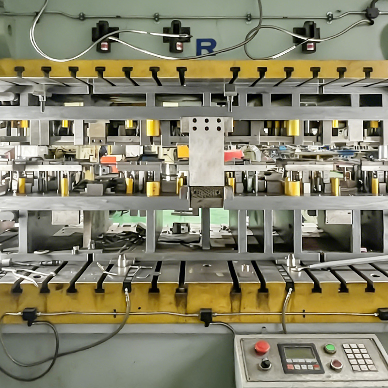 Progressive Molds for Automotive Motor Housings and Small PartsHigh-volume progressive stamping mold for automotive motor housings, suited to precision production where part complexity and annual volume justify progressive tooling.View Product →
Note where the crossover sits. Below roughly 50,000 pieces a year, tooling amortisation dominates and the manual route still wins on total cost. Between 50,000 and 150,000 the answer depends on part complexity and whether a second part number can share the same strip — that shared-strip option is frequently what makes a progressive tool pay back inside eighteen months.
Three Hidden Metrics That Decide Line Profitability
Quotations usually show piece price and tooling cost. They rarely show material utilisation, overall equipment effectiveness or the scrap rate after a tool has been reground twice. Those three numbers frequently differ by more between two suppliers than the quoted price does.
Progressive
OEE 76%
Transfer
OEE 61%
Manual cell
OEE 44%
OEE for a progressive line reflects three things working together: press availability, the feed and coil-change discipline, and first-pass yield. A line that runs at 60 strokes per minute but stops every forty minutes for a jam typically loses to one running at 45 strokes per minute with a clean scrap path. When comparing suppliers, ask for the actual coil-change time, the pitch and stroke rate, and the number of parts between regrinds — not the maximum press speed.
Where Automotive Progressive Stamping Parts Are Used
Progressive work dominates the high-volume sections of a vehicle rather than the whole structure. The distribution below reflects typical part families produced on progressive and multi-station tooling.
- EV and powertrain — 42%: motor housings, battery cover plates, high-voltage copper busbars and drive-unit brackets.
- Body, seat and structure — 24%: seat frames, reinforcement brackets, latch plates and small body members.
- Fuel, exhaust and commercial vehicle — 18%: tank end plates, heat shields and heavy-truck bracketry.
- Electronics and industrial equipment — 16%: server chassis, oven shells, laptop and phone structural parts, servo-drive housings and compressor components.
 New Energy Vehicle Copper Busbar Stamping PartsPrecision-stamped high-purity copper busbars for EV high-voltage current distribution, relevant where conductive, low-resistance connections and adjacent automotive stamping demand close supplier integration.View Product →
The copper busbar family is worth calling out. Those parts combine a soft, highly conductive material with a demanding burr and flatness specification, and they are often produced at the same time as the surrounding steel parts on adjacent equipment. A supplier who already runs both automotive stamping parts and electronic stamping work usually has the toolroom and the metrology depth to handle both material systems without a long learning curve on the first run.
Specifying a Progressive Stamping Programme: Seven Steps
Most cost overruns on progressive programmes come from sequencing, not from the die itself. The order below reflects how the design, tooling and automation decisions actually constrain one another.
- Fix the strip layout first. Set pitch, web and coil width against the blank geometry before choosing station count. Every later decision inherits this geometry.
- Assign tolerances to stations. Decide which station owns hole position, which owns the bend angle, and which owns flatness. Vague drawing tolerances become disputes during PPAP.
- Size the press with margin. Calculate peak shear force, not average force, and keep 20 to 30 percent headroom for a future material upgrade.
- Decide the automation scope early. Coil loading, straightener, feeder, scrap conveyor and exit handling all change die height and cycle timing if they arrive late in the project.
- Run a die simulation. Forming simulation catches springback and thinning before steel is cut, which is far cheaper than correcting a finished form station.
- Plan the regrind cycle. Record the number of parts between sharpenings from the first production day so tooling life becomes a measurable cost line instead of an assumption.
- Verify on production tooling. Build off-tool samples and full PPAP on the final die, not on a prototype tool, or the tolerance stack will move once the real strip arrives.
 Custom Stamping Automation Equipment for Progressive Stamping LinesProduct listing for custom stamping automation equipment, relevant where progressive programmes need coordinated die design, stamped part production and automation delivery.View Product →
Step four is where turnkey delivery changes the maths. When the die builder and the automation builder sit under one contract, die height, pass line, feeder stroke and press tonnage are resolved on a single drawing rather than negotiated between two vendors after the tool is already cut. Keeping die design, stamped part production and stamping automation inside one engineering group removes the interfaces where progressive programmes typically lose weeks.
Maintenance, Tolerance Retention and Compliance Records
A progressive die that produced acceptable parts at launch will not stay there without a maintenance rhythm. Typical practice is to measure a sample at every regrind interval, track the trend rather than the individual reading, and replace guide pillars and bushings on a fixed count rather than on failure. The cost of a planned eight-hour die service is a fraction of the cost of a scrapped coil and a missed shipment.
Compliance documentation for automotive stamping usually needs to travel with the part: material certificates with heat numbers, dimensional layout reports at PPAP, control plans identifying the critical stations, and records of die maintenance and regrind history. High-strength steel grades supplied to a 590 MPa or 780 MPa specification should have incoming inspection data recorded against the coil, because the forming window for those grades is narrow and a mill-to-mill variation will show up as a bend-angle shift long before it shows up as a visible crack.
Lubrication and scrap management are the two housekeeping items that most affect long-run tolerance retention. Correct lubricant selection for the coating on the incoming strip reduces galling at the draw stations, and a scrap chute that is inspected on a fixed schedule prevents the slug-induced die damage that no amount of press capacity can absorb. Treated as routine maintenance rather than as an afterthought, both extend the interval between regrinds and hold the tolerance band that made progressive stamping the right choice in the first place.
Previous Post
Heavy Stamping Guide: Tolerances, Tonnage, Die Design, and Tooling Selection
Next Post
In-Die Riveting for Progressive Stamping Dies: Principles and Applications
Our Products.
Start Your Business with an OEM Manufacturer Right Here!

Provide global customers with complete turn-key solutions
through
innovation!
QUICK LINKS
CONTACT INFO.
-
 +86-139 1308 8972
 -

-
 No. 118 Yexin Road, Wujiang Economic Development Zone, Suzhou, China
Copyright © Suzhou Shuangqisi Mold Equipment Co., Ltd. All Rights Reserved. Custom Stamping Die Metal Stamping Die Manufacturers
